11
IMPORTANT!
For all flue systems, a restrictor
may need to be inserted into the
boilers flue connector; the
restrictor must be ø 42 in
diameter depending on the length
of piping indicated in Table 2.1.
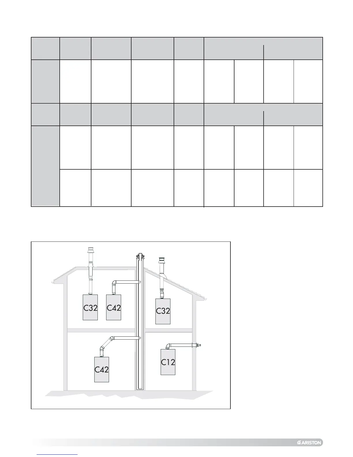
The diagrams illustrate some of the
various designs for coaxial or twin
pipe flue systems (F
IG.2.11 &
FIG.2.12).
For further information on
discharge/ventilation accessories,
see the F
LUE PIPE ACCESSORIES
MANUAL.
Exhaust
Type
C12 (xy)
C32 (xy)
C42 (xy)
C52 (xy)
C82 (xy)
Restrictor
ø 42 mm
L max = 11 m
L max = 18 m
Maximum
Extension
Exhaust/Air
42 m
42 m
42 m
43 m
NO
Restrictor
L min = 11 m
L max = 42 m
L min = 18 m
L max = 43 m
Risk of Condensation Forming
Twin Pipe
Systems
ø 80/80
Piping not insulated
ø 42
restrictor NO
5 m 5 m
5 m 5 m
Piping insulated
ø 42 restrictor NO
5 m 5 m
16 m 16 m
L = Sum of the total length of exhaust + air intake piping.
COAXIAL SYSTEMS
FIG. 2.11
Exhaust
Type
C12 (xx)
C32 (xx)
C42 (xx)
Restrictor
ø 42 mm
L min = 0.5 m
L max = 1 m
Maximum
Extension
Exhaust/Air
L = 3 m
NO
Restrictor
L min = 1 m
L max = 3 m
Risk of Condensation Forming
Coaxial
Systems
ø 60/100
Piping not insulated
ø 42
restrictor NO
NONE NONE
Piping insulated
ø 42 restrictor NO
NONE NONE
TABLE 1.0