2 ATS4000 Installation and Quick Programming Guide
INSTALLATION
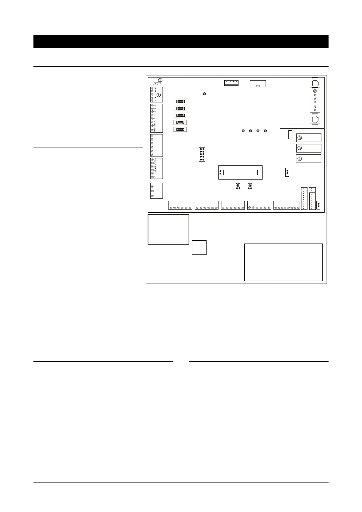
1. Control Panel
① Earth plug for shields from data
cable
② Eprom (Factory fitted)
③ Flash
④ RAM or IUM (optional)
⑤ TST1 restore master user code
⑥ TST 2 factory use only
J2-J6 Zones
J7 Interface to ATS1202 input
expanders
J8 Clock-out Interface to plug on
output expansion
J9 On board relay output.
J10 RS485 system databus and box
tamper connections
J11 Connector to printer or printer/PC
board (ATS3000/4000)
J13 Siren and strobe connections
J14 Auxiliary power output
J15 Not fitted
J16 PSTN line connection
J17 Power connections
J18 Serial connection (RS232)
J19 RJ11 PTT connection
J20 Connector to ISDN/Audio
Mains Power connection
Use the Mains Connector Terminal for connecting the mains-supply. A fixed cable or a flexible mains lead to an
earthed mains outlet can be used. In case fixed wiring is used, insert a dedicated circuit breaker in the power
distribution network.
IMPORTANT: Disconnect the mains power before opening the cabinet!
• Disconnect AC mains plug from AC Mains wall socket. or
• Disconnect the mains with the dedicated circuit breaker.
2. Important notes on mounting
Minimum clearance between equipment enclosures:
50 mm (between equipment vents)
Minimum clearance between enclosure and sidewall:
25 mm
✍ Only use units in a clean environment and not
in humid air.
3. LED’s
L1: Flashes slowly when the panel is operating
(the microprocessor is running)
Rx: Yellow LED flashes when remote units (RAS
and DGP) are replying to polling.
Tx: Red LED flashes when panel is polling remote
unit(s). It must always be active.
Rx1: Yellow LED flashes when data is being
received from a device connected to the PTT
line (J15/J16/J19) (central station or dialler
modem) or J18 (serial port (RS232 PC).
Tx1: Red LED flashes when data is being sent
from the panel to a device connected to the
PTT line (J15/J16) or J18 serial port.
J6
1 C 2 C 3 C
①
X
S+ S- S+ S- + -
F5
F4
F3
F2 F1
NC C NO
J5
4 C 5 C 6 C
J4
7 C 8 C 9 C
J3
10 C 11 C 12 C
J2
13 C 14 C 15 C16 C
J11
J7
RAM/IUM
FLASH
EPROM
J15
J19
J16
J18 J20
TST1 TST2
+12V
9-16
ISP
A B AX BX EA
KILL
12V RX TX 0V
J17
J14
J13
J10
J9
J8
Trans-
former
12 VDC Battery
Mains
Termina l
L1
RX
TX1
RX1
TX
 Loading...