6 ATS4000 Installation and Quick Programming Guide
Siren outputs
The internal and external siren speaker outputs on the
ATS control panel, are always treated as output 16.
On DGP’s with siren speaker outputs, the last of the 16
output numbers associated with that DGP address is the
siren output. For example, on DGP3 the siren speaker
output is output 64 (see table 4).
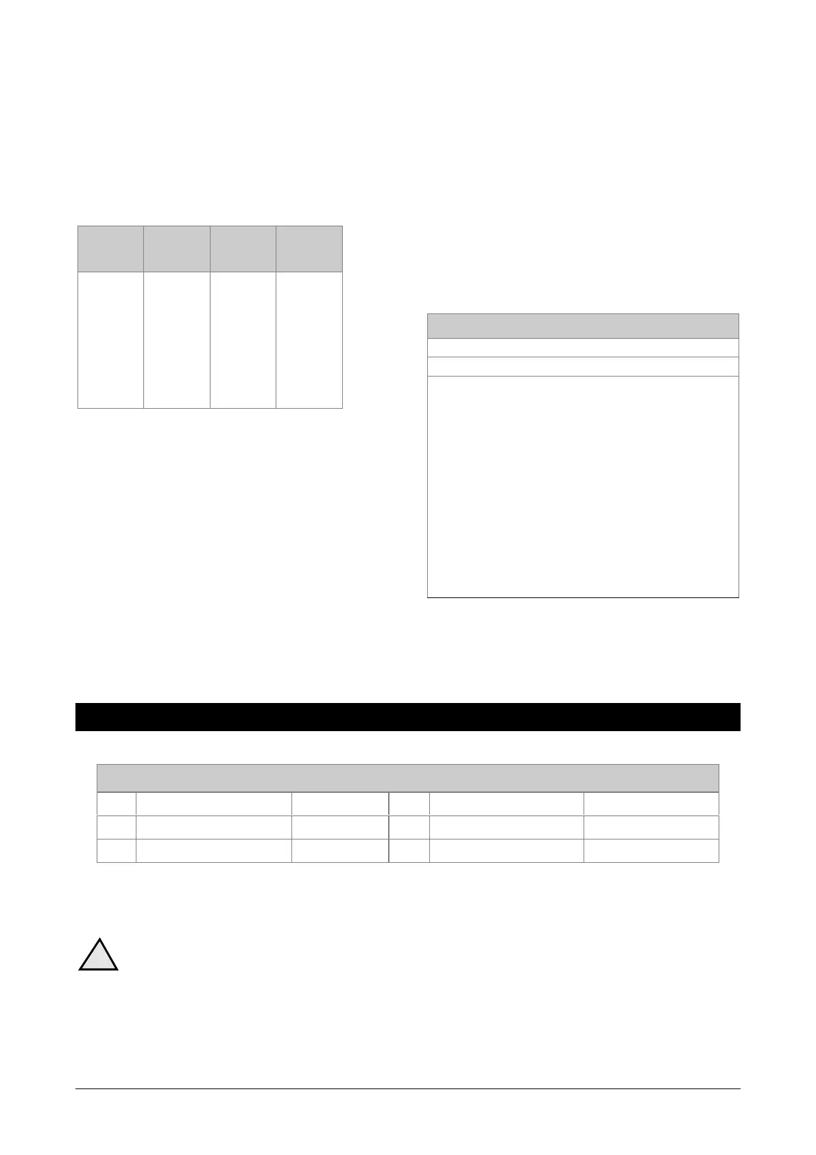
Table 4: Siren output numbers
DGP no. Siren
output
no.
DGP no. Siren
output
no.
1
2
3
4
5
6
7
8
32
48
64
80
96
112
128
144
9
10
11
12
13
14
15
160
176
192
208
224
240
-
To enable the siren speaker output, the output number
representing the siren output must be assigned to the
required "Siren Event Flag Number". The "Siren Event
Flag Numbers" are programmed in programming menu 2
– Area Databases.
Output control groups
Output control group numbers are a way of identifying a
group of eight outputs controlled by the control panel, a
DGP or an arming station.
When an output control group is assigned to an arming
station, the Open Collector output (or "OUT") terminal
follows the FIRST output of the output control group.
For further information refer to programming menu 3 -
Arming Stations.
Door and lift numbering
Door numbers are determined by the address of the
arming station or reader connected to the ATS system
databus or 4-Door DGP local databus, and the 4-Door
DGP address if applicable.
Doors 1 to 16 are reserved for arming stations 1 to 16
that are connected to the ATS system databus and used
for door control functions.
Doors 17 to 64 are used for door or lift numbers that are
controlled by a 4-Door/4-Lift DGP (ATS1250 or
ATS1260). See table 5.
Table 5: Door/Lift numbers allocated to each DGP
Unit Door number
RAS 1 to 16 1 to 16 (Door only)
Door or Lift 1
st
2
nd
3
rd
4
th
DGP1 17 18 19 20
DGP2 21 22 23 24
DGP3 25 26 27 28
DGP4 29 30 31 32
DGP5 33 34 35 36
DGP6 37 38 39 40
DGP7 41 42 43 44
DGP8 45 46 47 48
DGP9 49 50 51 52
DGP10 53 54 55 56
DGP11 57 58 59 60
DGP12 61 62 63 64
TECHNICAL SPECIFICATIONS
FUSES
F1 Ext. siren + strobe 1A, slow 20x5 F4 Aux. Power supply 2A, slow 20x5
F2 Switched aux. Power 2A, slow 20x5 F5 Battery 3A, slow 20x5
F3 System databus 1A, slow 20x5 Mains Fuse * 630mA, fast 20x5
• Mains Fuse is part of the mains terminal block.
WARNING! Before removing this fuse, mains power must be disconnected (see page 2)!
!
 Loading...