10
mains supply (210 - 250 volt)
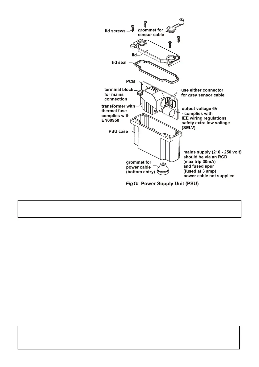
Fig15 Power Supply Unit (PSU)
Next, open the PSU case by un-
screwing 4x posi-drive screws; the
lid & seal should separate from the
PSU case. Slide out the PCB (Print-
ed Circuit Board) from the case.
With the mains power switched off,
prepare the mains power cable (not
supplied). This should be exible 3A
rated 2 core cable. Carefully remove
about 100mm of outer cable sheath-
ing, strip the wire ends back by
about 5mm.
Feed the cable through the grommet
at the base of the case (cut small slot
in grommet rst).
Connect the appropriate mains wires
to the L (Live) & N (Neutral) marked
on the terminal block on the PCB.
Slide the PCB back into the case
(note guide slots), allowing the
mains wires to rest in-front of the
transformer.
DO NOT leave wires on top of the
transformer as this may prevent the
lid from closing completely
Locate the end of the second cable (grey with black line) which is attached to the rear of the sensor
(cable end has connector tted, length is 750mm). The cable can be slid into the upper grommet (which
is pre-slit) & fed through the lid.
Plug this cable into either one of the two connectors on the PCB. The lid can now be closed, ensure the
grommet is pressed into the lid. Check that no cables are trapped under the lid, make sure the lid seal
is in place, and then ret the 4 retaining screws.
A pair of self-adhesive Velcro-type pads are provided. Attach one to the side of the PSU case & the other
to a suitable location on the rear of the mounting panel.
Note: ensure the selected location does not stretch/stress the cables. Consideration should also be
given to keeping the PSU case within easy reach/access for maintenance staff. Fasten the PSU case
to the mounting panel.
This completes the behind-panel installation work.
IMPORTANT: Leave the sensor protective sticker in place for at least 20 seconds after
powering-on the product.
See section 8 regarding sensor adjustment
IMPORTANT: Ensure terminal block screws are rmly tightened & clamp the wires securely.
Note earth connection is not required to PCB