9
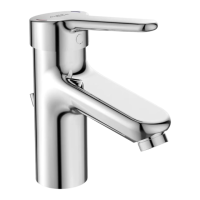
Fig13 View from rear showing solenoid valves link cable fitted
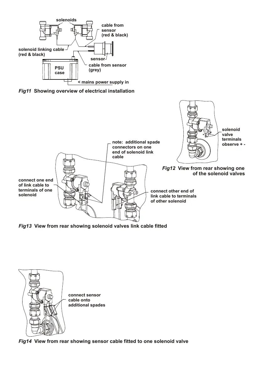
Fig12 View from rear showing one
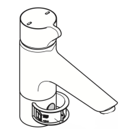
Fig14 View from rear showing sensor cable fitted to one solenoid valve
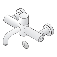
Fig11 Showing overview of electrical installation
Connection of this product to mains
power supply should be undertaken by a
competent person and should conform to
IEE Wiring Regulations.
A typical example of an installation of a prox-
imity mixer is shown here as a guide.
Orientation & position of solenoids, and PSU
(Power Supply Unit) case can differ from in-
stallation to installation.
An overview of the electrical wiring is shown
in Fig 11
With the product securely mounted to the panel &
plumbed-in, electrical work can commence.
First connect the two solenoid valves together using the separate link cable provided. The link cable is
black & red with connectors tted at both ends. Cable length is 500mm.
Connect the cable to the solenoid valve terminals as shown. Observe the + and – symbols marked on
the solenoid valves, connect the red cables to + & black to -.
Note: one end of this link cable is tted with additional spade connectors
as shown. These connectors are for attaching the red & black sensor cable.
Locate the end of the red & black cable which is attached
to the rear of the sensor. Cable length is 750mm.
Connect this cable to the spade connectors shown on
the link cable. Observe + and – Ensure red is connected
to red & black to black.