21
13 INTEGRAL VALVES
The integral isolation valves facilitate a number of activities:
• Cleaning strainers
• Servicing the thermostatic cartridge
• Connecting hose for integral thermal disinfection
• Audit cold water isolation test
• Demounting the mixer from its inlets
• Control ow during hydro-purge
Check valves
To prevent back siphonage of water to the supply pipes, check valves are tted inside the inlet tails
(19) – see gure 27. These check valves can be maintained/replaced, but MUST NOT BE REMOVED.
Strainers
*To achieve a suitable ow rate where supply pressures are very low it may be necessary to remove the
ow regulator (item 10 gure 27).
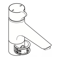
Figure 25 In-line isolating valve with filter
10
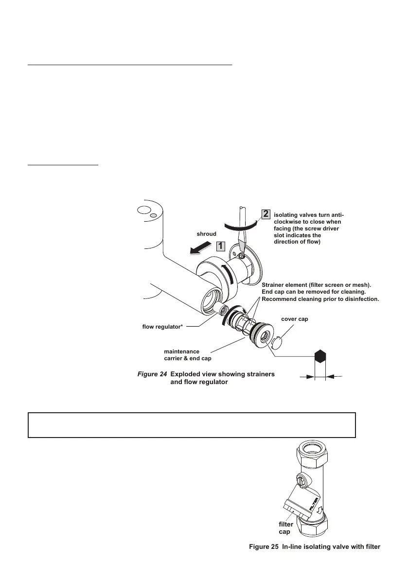
isolating valves turn anti-
Strainer element (filter screen or mesh).
End cap can be removed for cleaning.
Recommend cleaning prior to disinfection.
Figure 24 Exploded view showing strainers
and flow regulator
13.2 MAINTENANCE OF IN-LINE COMPONENTS
In this example, (see figure 25) the isolator screw slot is
shown in the vertical position. This indicates the valve is open.
To close this valve, rotate the isolator screw by 90° into the hor-
izontal position. By operating the product, this will drain down
the water from the pipes below the service valve. Once the
product has been isolated, this will permit maintenance staff to:
1. Check & clean the lters by unscrewing the lter cap.
2. Replace the in-line solenoid valves if necessary.
3. Completely remove the product from the panel if necessary.
13.1 ISOLATING VALVES
NOTE: The ow regulator tted in each maintenance carrier is nominally rated 5L/min. Therefore
mixer is ow regulated to max 10L/min
To ensure trouble free opera-
tion of the tting, the strainer
elements should be checked
and cleaned in accordance
with the commissioning and
servicing guide (see section
9 & 10).
To access the strainer ele-
ment, rst unscrew and slide
back the shrouds and close
the isolation valves. Prise
out the cover cap then un-
screw the end cap using a 10
mm Allen key and withdraw
the maintenance carrier. The
strainer element should be
washed with clean water and
retted.
IMPORTANT NOTE:
The integral isolating valve(s) shown below should be used regularly for all servicing & testing of this
product. This is in preference to using any external inline isolating valves which may have been tted
upstream of the inlet legs. Regular exercising of both isolating valves is essential.