22
14 INTEGRAL THERMAL-DISINFECTION
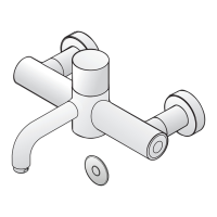
This tting is equipped with a disinfecting feature, which allows an engineer to feed water from the hot
inlet via a temporary by-pass hose* into the cold inlet. This hot water then passes through the cold inlet,
the thermostatic mixing chamber and out through the mixed water outlet. The temporary bypass hose is
inserted into special valve connectors in the inlet tails normally concealed by the shrouds.
Safety Note: Care should be taken when carrying out the following procedure to avoid
contact with hot water and hot surfaces. We recommend the use of protective hand wear.
To disinfect the tting proceed as follows:
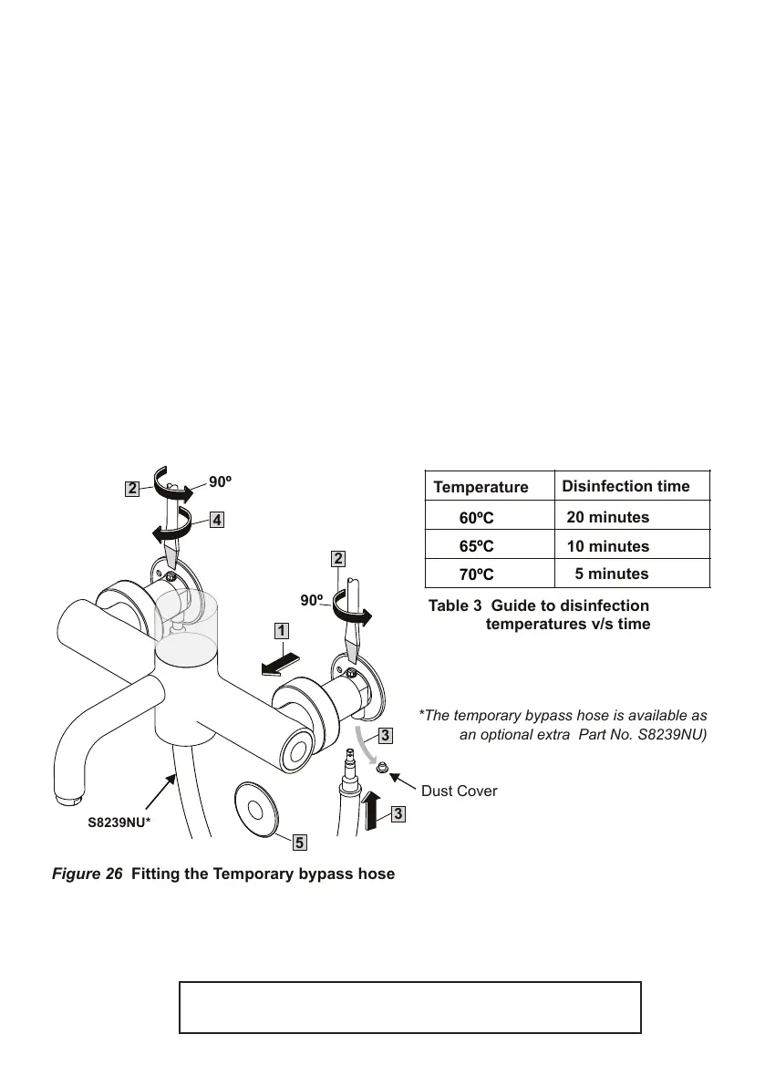
1. Unscrew the wall shrouds (42) and slide forward
2. Isolate both inlets by turning the isolation valves through 90 anti-clockwise.
3. Remove dust covers from the exposed nipples and push-t the temporary exible hose inserting the
cold side rst and then the hot.
4. Now turn hot side isolating valve 90 deg clockwise.
When the tting is operated hot water will now be able to pass from the hot inlet, through the by-pass
hose into the cold inlet and thence into the thermostatic mixing chamber and spout. Here, by the nature
of the thermostatic element, it will fully open the cold port. The hot water will then discharge to waste via
the tting’s spout, with a noticeable increase in surface temperature of the product.
5. Operate the tting using the proximity sensor. (As ow will stop after 60 secs it will be necessary to
start the ow using the sensor a number of times to produce ow time indicated in Table 3.)
Following the recommended disinfection period, turn the hot isolation valve back to the isolation posi-
tion, turn off the tting and remove the bypass hose - hot side rst then the cold. Turn both isolation
valves back to the normal ow position. Check for normal operation of the tting and replace dust caps
and shrouds.
Table 3 Guide to disinfection
*The temporary bypass hose is available as
an optional extra Part No. S8239NU)
Figure 26 Fitting the Temporary bypass hose
NOTE: Thermal disinfection will only have occurred if water has been
discharged from the spout according to the table 3 above.