2
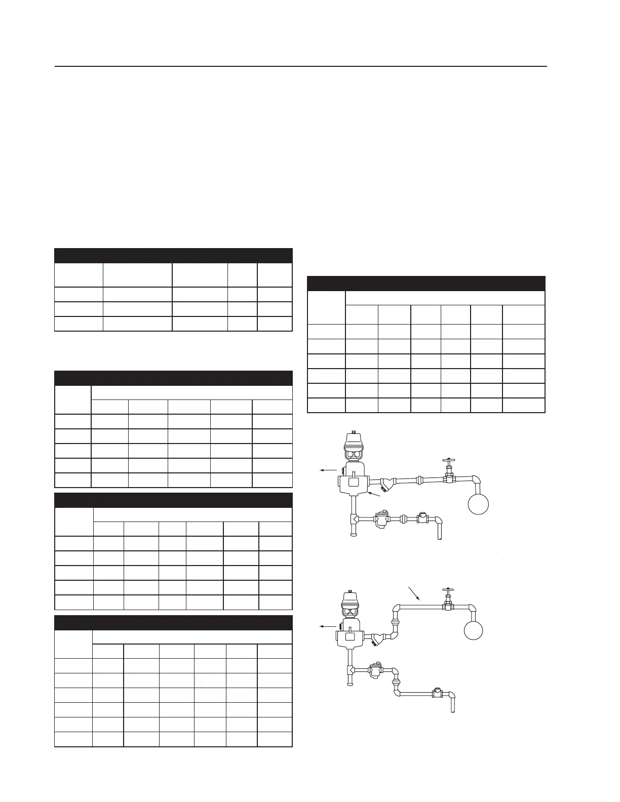
Step 3. Run the steam supply line from the steam
header to the humidifi er as indicated in Fig. 2-1. Observe
the following:
A. Take steam supply line from the top of the supply
main – never from the side or bottom. If several
humidifi ers take steam from a single supply line,
be sure to trap the end of the run-out with an Arm-
strong Trap of suitable size. If the steam supply is
very wet, install a drip pocket or separator ahead
of the humidifi er.
B. Size supply line in accordance with Table 2-1. If
the steam supply is 5 psi or less, it is advisable to
use one pipe size larger and reduce the pipe size
just ahead of the strainer and humidifi er.
C. Pitch the supply line in the direction of fl ow.
Humidifi er Piping
D. Expansion and Contraction. With average length
of supply line, the dimension change from hot to
cold should not exceed 2”. Provide piping with 3
elbows to get swing to take care of expansion and
contraction (See Fig. 2-2).
E. Clean piping. After running the supply line, blow
down at full steam pressure to eliminate dirt and
pipe cuttings.
F. A Pipe Strainer is furnished with each humidifi er.
Install (after blowing down supply line) as indi-
cated on drawing.
G. Swivel connections may be desirable – see
Fig. 2-2 and explanatory captions.
H. Pressure Reducing Valve. If required refer to
Fig. 3-1 and explanatory captions.
Table 2-1 Recommended Pipe Sizes
Humidifi er
Size
Supply Header
to Strainer
Steam Inlet
& Strainer
Drip
Leg
Trap
Piping
91 3/4” 3/4” 1” 3/4”
92 3/4” 3/4” 1” 3/4”
93 1-1/4” 1-1/4” 1-1/4” 3/4”
Steam Pipe Capacities
For computing ability of piping to deliver an adequate supply of steam to
humidifi er. Capacities shown are in pounds per hour.
Table 2-2 Steam Pipe Capacity at 5 psi
Pipe
Size in.
Pressure drop, psi per 100 ft. of pipe length
1/8 1/4 1/2 3/4 1
12431 44 54 62
1-1/4 52 68 97 120 140
1-1/2 81 100 150 180 210
2 160 210 300 370 430
2-1/2 270 350 500 610 710
Table 2-3 Steam Pipe Capacity at 15 psi
Pipe
Size in.
Pressure drop, psi per 100 ft. of pipe length
1/8 1/4 1/2 3/4 1 2
1 27 38 53 65 76 110
1-1/4 59 83 120 140 160 230
1-1/2 91 130 180 220 260 360
2 180 260 370 450 520 740
2-1/2 300 430 600 740 860 1210
Table 2-4 Steam Pipe Capacity at 25 psi
Pipe
Size in.
Pressure drop, psi per 100 ft. of pipe length
1/8 1/4 1/2 3/4 1 2
3/4 15 21 30 37 43 60
1 30 43 61 75 86 122
1-1/4 67 95 130 160 190 260
1-1/2 100 140 210 250 290 410
2 210 300 420 510 590 840
2-1/2 340 490 690 850 980 1380
Table 2-5 Steam Pipe Capacity at 50 psi
Pipe
Size in.
Pressure drop, psi per 100 ft. of pipe length
1/4 1/2 3/4 1 2 5
3/4 27 38 47 54 76 120
1 54 77 94 110 150 240
1-1/4 120 170 210 240 340 530
1-1/2 180 260 320 370 520 830
2 370 530 650 750 1060 1680
2-1/2 620 870 1070 1240 1750 2760
Figure 2-1.
Figure 2-2.
Strainer
Steam
Trap
Dirt
Pocket
Check
Valve
Take off top o
steam supply
To low
pressure return
Pitch down 1/2" in 10'
Typically pneumatically controlled humidifier installation.
Strainer
Steam
Trap
Dirt
Pocket
Check
Valve
To low
pressure return
Take off top of
steam supply
Pitch down
1/2" in 10'
Swivel connections shown above permit direction of discharge
to be altered easily. Loosen both unions, adjust direction, then
retighten unions.