3
Step 4. Install the Armstrong Steam Trap and connect
the trap to the return header. It is important:
A. To provide a dirt pocket ahead of the trap as
shown in the drawings.
B. To make sure the return header pressure is well
below the steam supply pressure. Never connect
a humidifi er trap to a line carrying returns from
high pressure traps.
Step 5. Install Fan and Motor of AMAF, AMEF, and FSA
units. The bracket is located on the side opposite the
steam discharge outlet in the humidifi er cap. Cap screws
are provided.
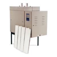
Step 6. Make Electric Connections for AMEF model fan
motors. Electrical connections are shown in double dash
lines in Fig. 3-2.
A. If automatic control of the fan motor is desired, in-
stall a pneumatic-electric relay. The relay should
be set to start fan with a 2 psi air signal.
See Fig. 3-2.
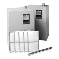
P.R.V. Installation. Reducing Valves. Where the steam
pressure available for humidifi ers is too high, a reducing
valve of the single-seated or dead-end type should be
used. The reducing valve should be at least 10 ft. from the
humidifi er. If the supply line is more than 20 ft. long, pro-
vide a drip pocket and extra trap just ahead of the pressure
reducing valve.
Relief Valve. A pressure relief valve between the humidifi er
and pressure reducing valve is a good insurance. Humidi-
fi er bodies are only rated for 60 psig steam service.
Pressure Gage. A pressure gage or connection for install-
ing a gage between reducing valve and the humidifi er may
save its cost many times over.
Air and Electrical Connections
10' Min.
Strainer
Steam
Trap
Steam
Trap
Steam
Supply
Dirt
Pocket
PRV
Relief
Valve
Pressure Gage
To Low
Pressure
Return
Check
Valve
Figure 3-1.
Motor
Compressed air hookup. Electrical connections for AMEF units are shown. For AMAF model omit electric.
Compressed air hookup showing air powered fan and air line accessories for AMAF units.
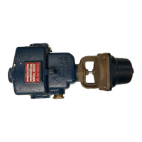
Wiring diagram for standard 120V or
240V FSA or VSA Humidifiers.
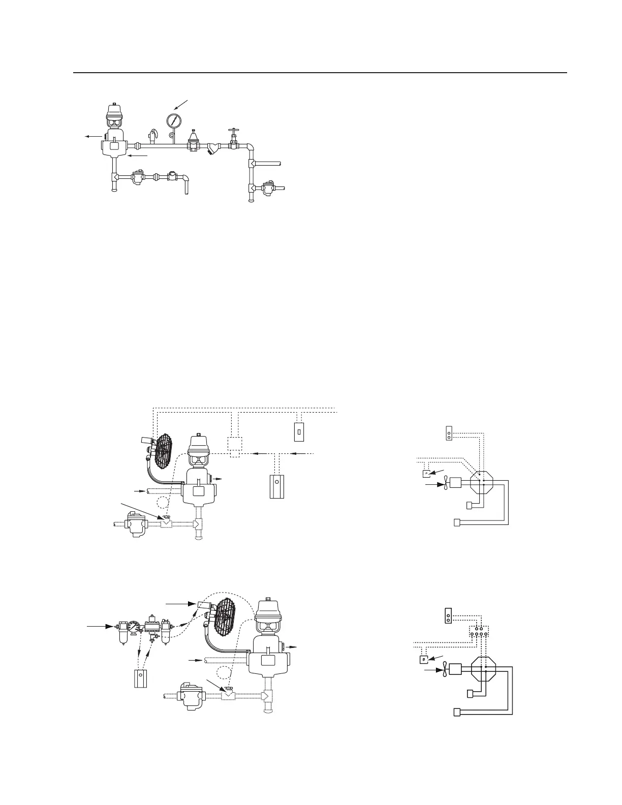
Wiring diagram for 120V or 240V VSA
Humidifier with 24V line to humidistat.
Steam In
Steam Trap
Steam
Trap
Pneumatic
Temperature
Switch
Pneumatic
Temperature Switch
Air Supply
Oiler
Air Fan Assembly
Steam In
Humidity
Controller
Filter
Steam
Out
120 V 240 V Line In
P.E. Switch
Humidity
Controller
Hand
Switch
Armstrong A-8581-A
(HC-101) Humidity
Controller
Armstrong A-8581-A
(HC-101) Humidity
Controller 24 V
Power Source
Power Source
Solenoid Coil
Solenoid Coil
Temp. Switch
Temp. Switch
Switch
Fan
(when used)
Junction
Box
Junction
Box
Relay
Air
In
Switch
Fan
(when used)
Figure 3-4.
Figure 3-3.
Figure 3-5.
Figure 3-2.