6
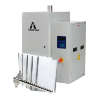
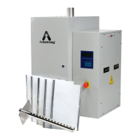
How electrically operated units work.
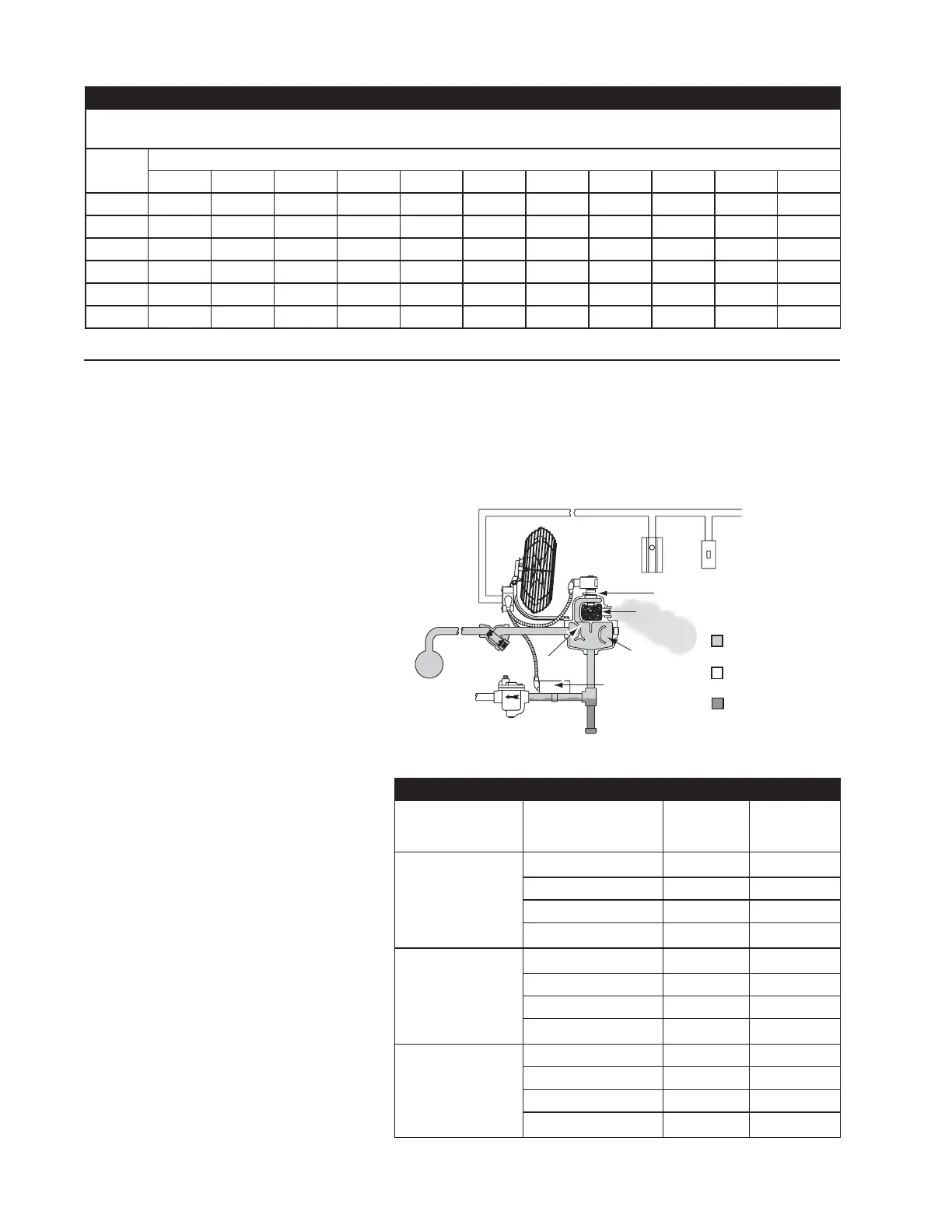
After passing through the Armstrong inline
strainer, steam enters the cast iron steam-
separating chamber. The use of cast iron
as a separator is probably the single most
important feature in the Armstrong humidi-
fi er design.
The preferred material of strength and
durability, case iron gives Series 9000
humidifi ers fl exibility in design without
fabrication. In addition, castings mean
better heat retention because of thicker
walls. Which in turn means a lower rate of
condensation.
Entering the main separating chamber,
steam encounters a cupped baffl e which
reverses its fl ow and turns it back on itself.
The outer walls of the casting form another
cup, and the same thing happens again.
These two 180° turns help condition the
steam, reducing its volume and separating
the condensate from the vapor. Conden-
sate from supply and radiation and most of
the particulates in the steam not removed
by the strainer collect in the large drain leg
and are discharged through the inverted
bucket drain trap.
Steam from the separating chamber fl ows
around and through the solenoid valve
which is actuated by a demand signal from
the humidistat. (Solenoid can be ex-
changed for electric or pneumatic control
if desired by choosing an operator and
bonnet assembly).
Next the steam fl ows into the drying cham-
ber which is jacketed by the separating
chamber. The drying chamber is fi lled with
a stainless steel silencing material which
almost completely absorbs the noise of
escaping steam. Dispersion is through a
jet nozzle or by a fan.
How air-operated units work.
Air-operated units operate in the same
manner as electric units except that they
Operation
Figure 6-1.
utilize a pneumatic humidistat as humidity controller in the space and an
air operator to open and close the steam valve.
Explosion hazard humidifi cation.
Sizing air-operated humidifi ers for areas where an explosion hazard ex-
ists is done exactly as for other requirements except that they should be
sized for the most severe conditions of makeup air, RH required and
minimum steam pressure.
Table 6-1
75°F. Humidifi cation. Pounds of Steam Required Per Hour, Per Air Chcange for Each 1000 cu. FT. of Space to Secure Desired Indoor Relative
Humidity at 75°F. with Various Outdoor Temperature (Outside Air 75% Saturated).
Outdoor
Temp.
70°F. - RELATIVE HUMIDITY DESIRED INDOORS-70°F
25% 30% 35% 40% 45% 50% 55% 60% 65% 70% 75%
30 .129 .196 .264 .331 .399 .466 .533 .601 .668 .736 .803
20 .204 .271 .339 .406 .474 .541 .609 .676 .744 .811 .879
10 .254 .321 .389 .456 .524 .591 .659 .726 .794 .861 .929
0 .286 .354 .421 .489 .556 .624 .691 .759 .826 .894 .961
-10 .307 .374 .442 .509 .577 .644 .711 .779 .846 .914 .981
-20 .319 .387 .454 .522 .589 .657 .724 .792 .859 .927 .994
Strainer
Fan
Solenoid Valve Open
Humidistat
Switch
Separating
Chamber
Drying
Chamber
Temperature
Switch
Baffle
Steam
Trap
Steam
Supply
Condensate
Steam at
Atmospheric Pressure
Steam at
Supply Pressure
Table 6-2 Location of Unit Humidifi ers for Direct Discharge into Atmosphere.
Method of Steam
Dispersion
Maximum Discharge
Capacities in lbs. of
Steam per hour
Minimum
Ceiling
Ceiling
Clearance
30 8’ 2’
Electric Fan
80 10’ 3’
FSA, AMEF Models 200 14’ 6’
300 16’ 8’
30 10’ 3’
Air Fan
80 12’ 4’
AMAF Models 200 16’ 8’
300 20’ 8’
30 10’ 4’
Jet
80 12’ 6’
VSA, AM Models 200 20’ 10’
300 20’ 10’