Antenna Analyzer AIM4170 page 29
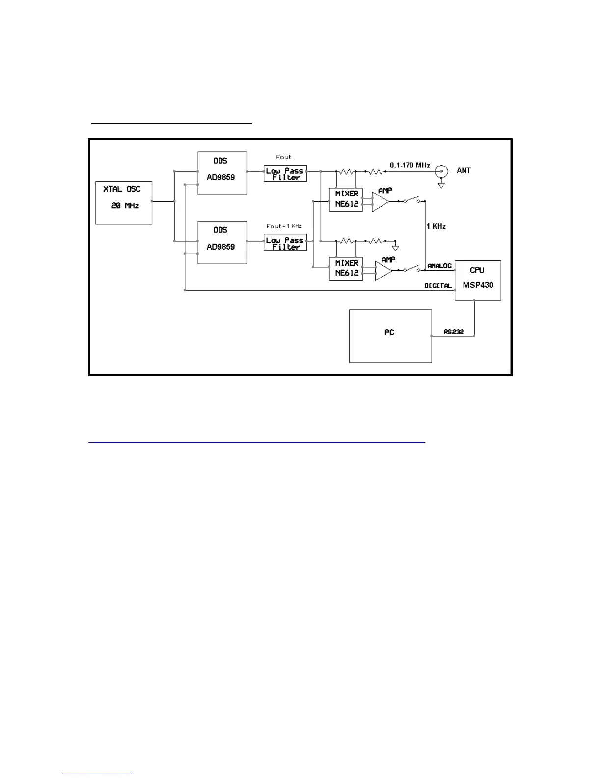
Block diagram of the AIM4170:
The AIM4170 uses two Direct Digital Synthesizer (DDS) chips. One generates the test
signal and the other acts as a local oscillator to heterodyne the RF signals to the audio
range. You can read about the basic principles of the DDS at this address:
http://www.analog.com/library/analogDialogue/archives/38-08/dds.pdf
A 20 MHz crystal controlled oscillator drives both of the DDS chips. Inside the DDS, the
clock is multiplied by a factor of 20, so the effective clock rate is 400 MHz. Program
frequency resolution is a fraction of a Hertz. The output of each DDS goes to a 170 MHz
low pass filter to remove the harmonics of the digitally generated signal. The output of
the low pass filter is a sine wave in the range of 0.1 MHz to 170 MHz. Any amplitude
variations or phase shift in the low pass filters do not affect the measurement accuracy
since they affect the current and the voltage channels equally and thus cancel out when
the ratio is taken.
The output of one DDS supplies the test voltage and current to the load impedance and
the other DDS acts as the local oscillator to heterodyne the voltage and current signals
down to 1KHz. Audio amplifiers boost the 1KHz signals and drive the input to the 12-bit
analog to digital converter (ADC) that is inside the MSP430 microprocessor. This
microprocessor is mounted inside the AIM4170 case. The raw data is sent from the
microprocessor to the external PC via the RS232 port. The PC calculates the various data
values and displays them graphically.