Antenna Analyzer AIM4170 page 28
AIM4170 Principles of Operation
The AIM4170 is based on the same technology used in the AIM430 and AIM4160.
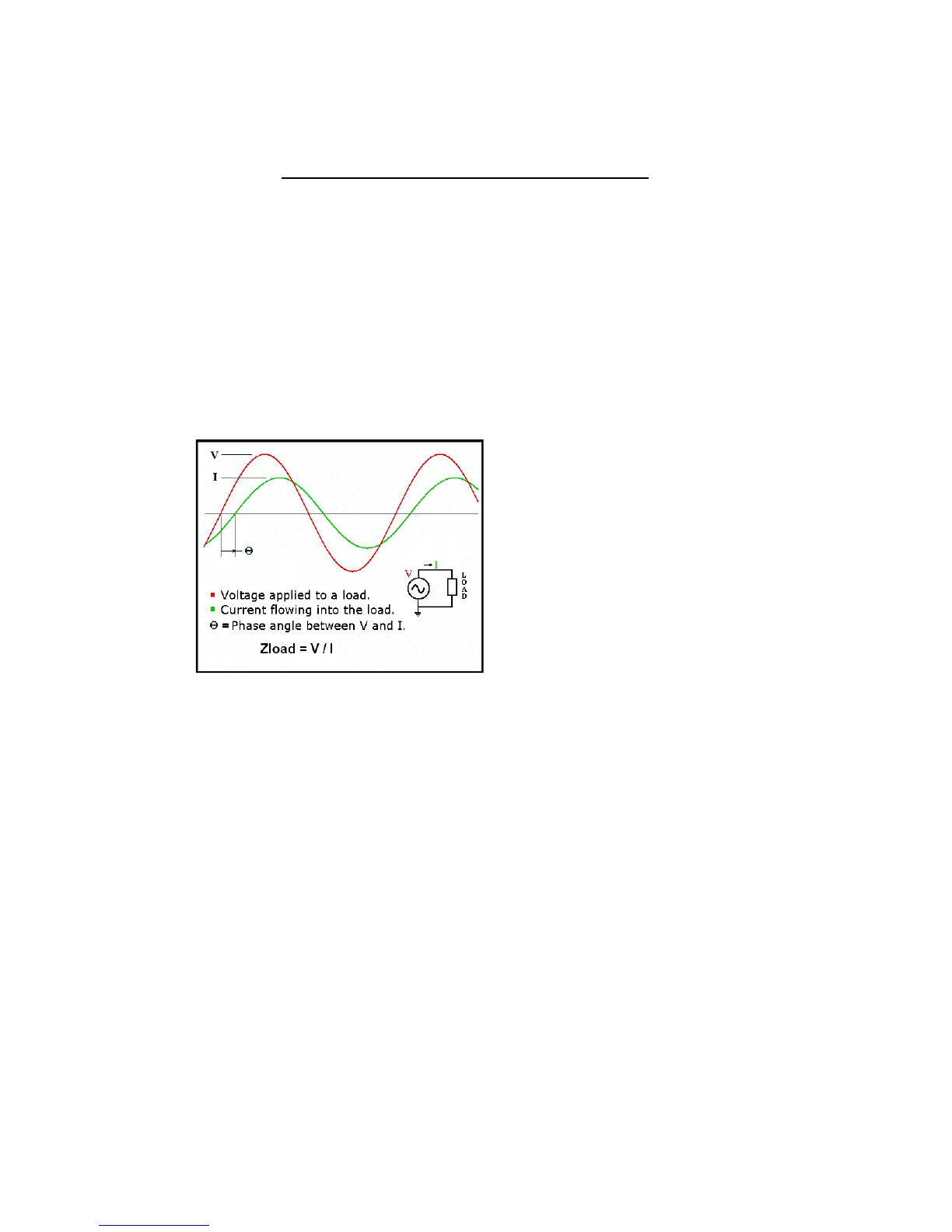
1. An RF voltage is applied to the transmission line input.
To reduce the chance for interference to nearby radio receivers, the maximum
output power is less than 20 microwatts (-17 dBm).
2. Measure the applied voltage and the current flowing into the load. The current is
measured across a precision resistor which has a much wider bandwidth than a
transformer. (The AIM4170 does not use any RF transformers). The current
sensing resistor does not have to be adjusted and it has excellent long-term
stability.
3. Calculate the magnitude and phase of the input impedance. The magnitudes and
phases of the applied voltage and resultant current are measured with an analog to
digital converter (12-bit ADC) and their ratio determines the magnitude of the
impedance. The sign of the phase is also measured so that capacitive and
inductive reactances can be distinguished.
4. The signal processing circuits are linear, so the nonlinearity problem inherent with
diode detectors is eliminated.
5. Calculate various parameters including: SWR, equivalent input resistance and
reactance, cable length, cable loss. A large number of parameters can be
calculated using the fundamental impedance measurement. The load is assumed
to be an antenna but the data is displayed in such a way that discrete capacitors
and inductors can be measured too. These values are plotted versus frequency
and the exact numeric data can be read by moving a cursor to the point of interest.