Antenna Analyzer AIM4170 page 21
Data Referred to Antenna
Sometimes it is desirable to know the impedance at the antenna terminals. Two different
methods can be used with the AIM4170. The method described first is more accurate but
it requires a careful calibration phase. The second method described later is not quite as
accurate but it only requires data from the manufacturer’s spec sheet.
METHOD A:
After a calibration phase where the properties (length and loss) of the cable are
determined at each measurement frequency, the measurement made at the transmitter end
of the line can be transformed to the antenna terminals. This is done in real-time during
the scan and the displayed data is very close to what would be measured if the analyzer
were actually mounted at the antenna. The transmission line can be any length.
First, click the “Limits” button at the bottom of the screen to specify the frequency range
and the frequency step you want to use.
To select this feature, click
Calibrate and then click
Cable.
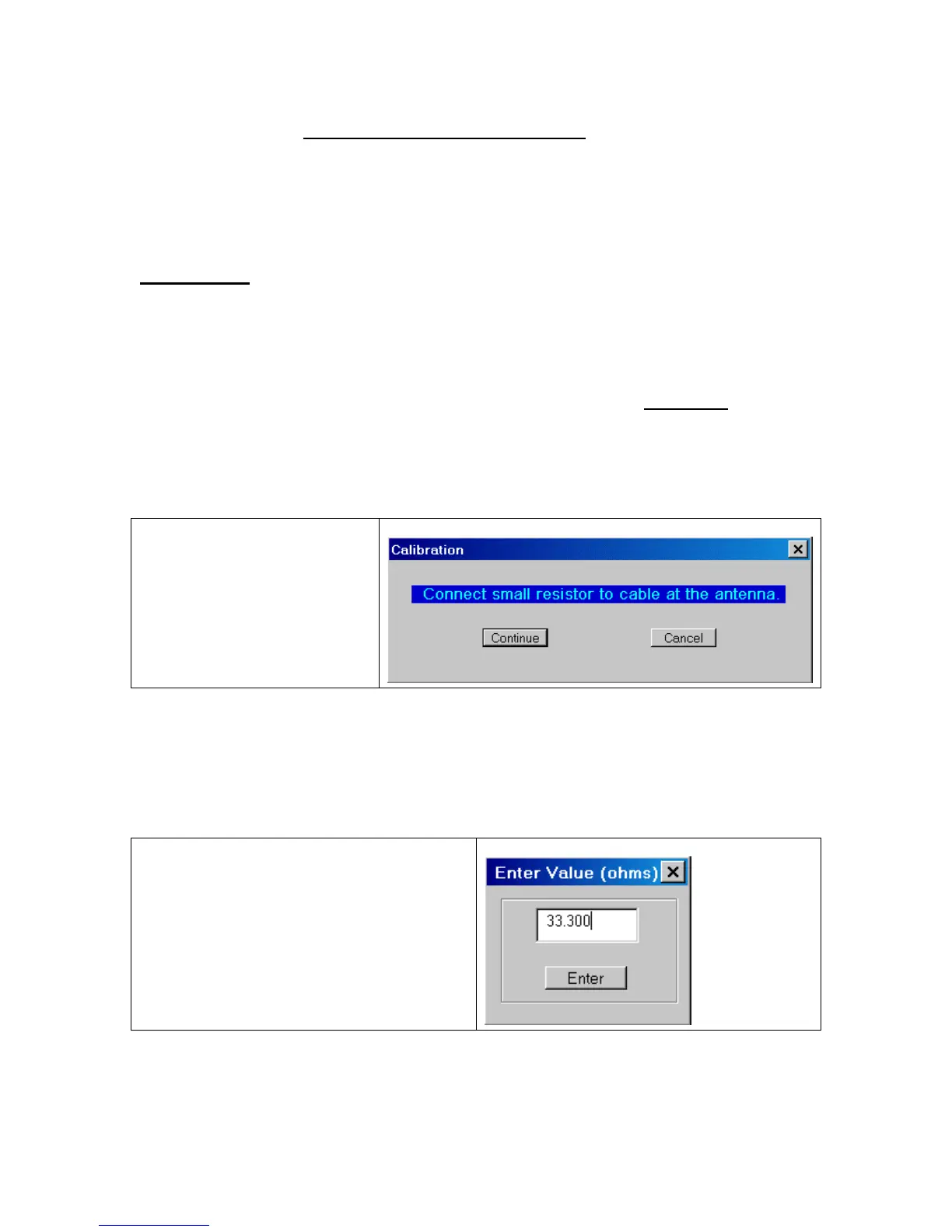
Disconnect the coax from the antenna. Then connect a small resistor in the range of 20 to
100 ohms at the antenna end of the coax. The actual value is not critical as long as you
can measure it accurately with a digital ohmmeter. The resistor can be a ¼ watt size since
it doesn’t have to handle any power. Click “continue” after the resistor is in place.
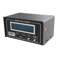
Enter the actual value of the resistor. The
last value that was entered will be
displayed as the default value.
The AIM4170 will now scan the specified frequency range and save a table of parameters
that contains information about the cable at each measurement frequency. This is more