Home
Array Solutions
Measuring Instruments
AIM4170
Page 48
Array Solutions AIM4170 - Page 48
58 pages
Manual
Save Page as PDF
To Next Page
To Next Page
To Previous Page
To Previous Page
Loading...
An
t
enn
a An
al
y
zer AIM4170
page 48
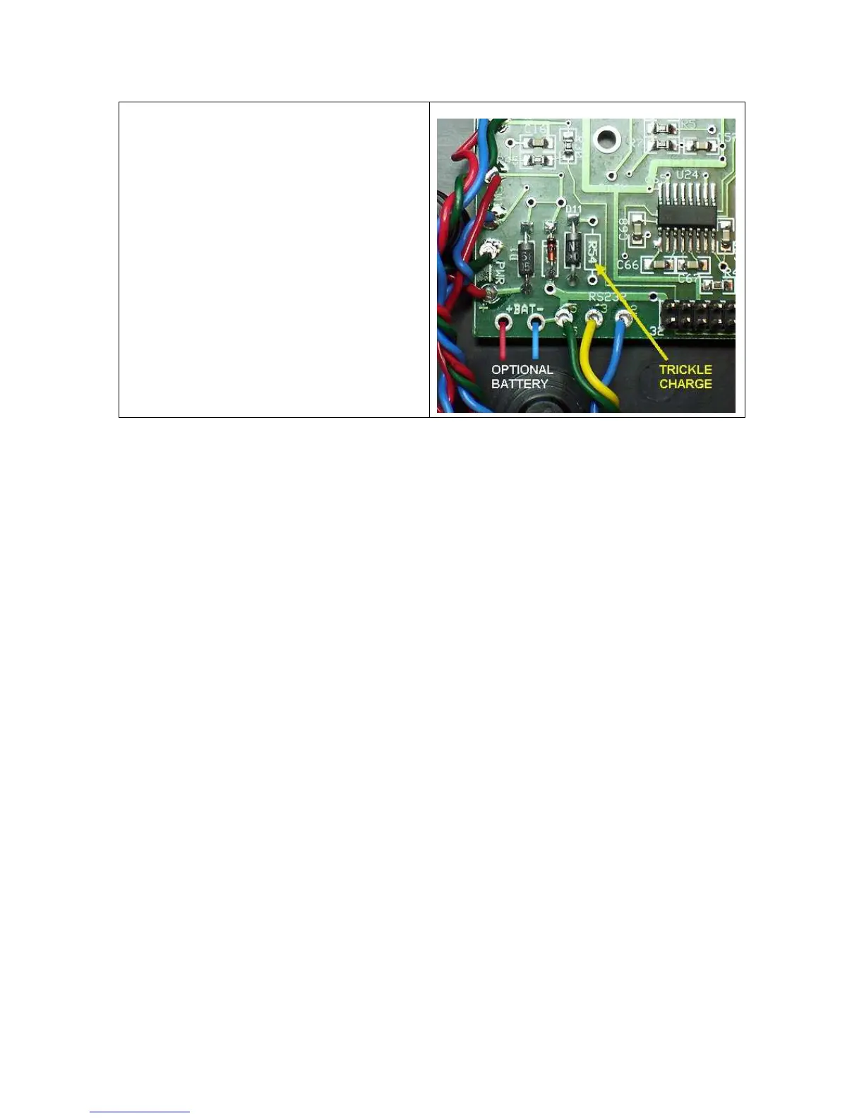
In the l
o
wer l
ef
t
co
rner o
f
the board are
sh
o
wn the po
s(+ RED)
and n
eg(-
BLUE)
ba
t
t
ery
co
nn
ections
.
D1 and D11 are i
ncl
uded o
n the PCB.
There i
s an open space
t
o
i
nstal
l
an
opt
i
o
n
al
R54 for chargi
ng a b
att
ery
.
47
49
Table of Contents
Main Page
Table of Contents
2
Quick Start
3
Calibration
7
Commands
11
Data Window
19
Data Referred to Antenna
21
Analyzer Principles of Operation
28
Measurement of Crystal Parameters
32
Frequency Source
36
Appendix 1 - Specifications
37
Appendix 2 - Complex Numbers
38
Appendix 3 - Hot Keys
42
Appendix 4 - RS232/USB Operation
43
Appendix 5 - Scan Data File Format
44
Appendix 6 - Battery Operation
47
Appendix 7 - Saving Screen Shots
49
Appendix 8 - Configuration File
50
Appendix 9 - Component Test Fixture
53
Terms and Conditions
55
Related product manuals
Array Solutions PowerMaster II
28 pages