Camera Body Overview 8
4 Camera Body Overview
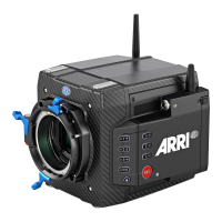
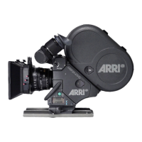
Camera Front
1
SERIAL Connector
2
LBUS Connector (on Lens Mount)
3
VF 1 Viewfinder Connector
4
Lens Mount (here: LPL Mount (LBUS))
5
LBUS Connector
SERIAL Connector (4-pin LEMO)
The SERIAL connector is used to connect distance measurement devices such as ARRI UDM-1, CE
CineTape Measure or Focus Bug directly to the camera and receives data from and provides power
to the distance measuring device. The SERIAL connector outputs regulated 12.0 V with a maximum
current of 200 mA.
VF 1 Viewfinder Connector (CoaXPress)
The camera uses an industrial CoaXPress interface with an ARRI custom connector to connect the
MVF-2 viewfinder with the camera. The interface transmits power, video and control data. The VF 1
connectors supports cable lengths of up to 5 m (16.4 ft). The VF connector supports hot plugging and
comes without a key, so the viewfinder cables plug in regardless of the connector's orientation.
LBUS Connector (4-pin LEMO)
The LBUS connector is used to connect daisy chainable LBUS devices of the ECS Electronic Control
System (lens motors, ARRI Master Grips, ARRI OCU-1) to the camera and supplies regulated 24.0 V
with a maximum current of 4.0 A.
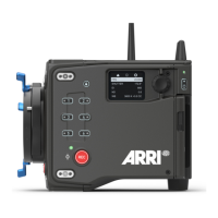
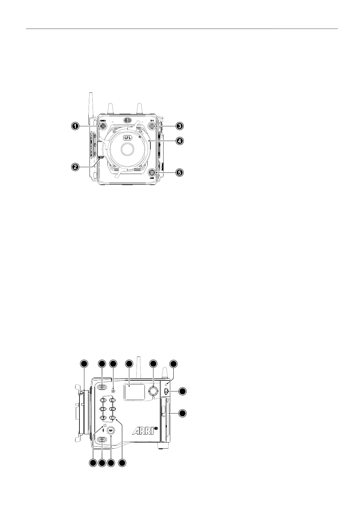
Camera Left
1
Lens Mount (here: LPL Mount (LBUS))
2
Mounting Points for Accessories
3
LOCK Button
4
Side Display
5
Side Display Jogwheel
6
Rear Camera Status LED
7
Left Camera Status LED
8
REC Button
9
User Buttons 1-6
10
POWER Button
11
Camera Identification Label
 Loading...