4
User Manual - Annex I
High Voltage Instrument Transformers | CA/UT/KA
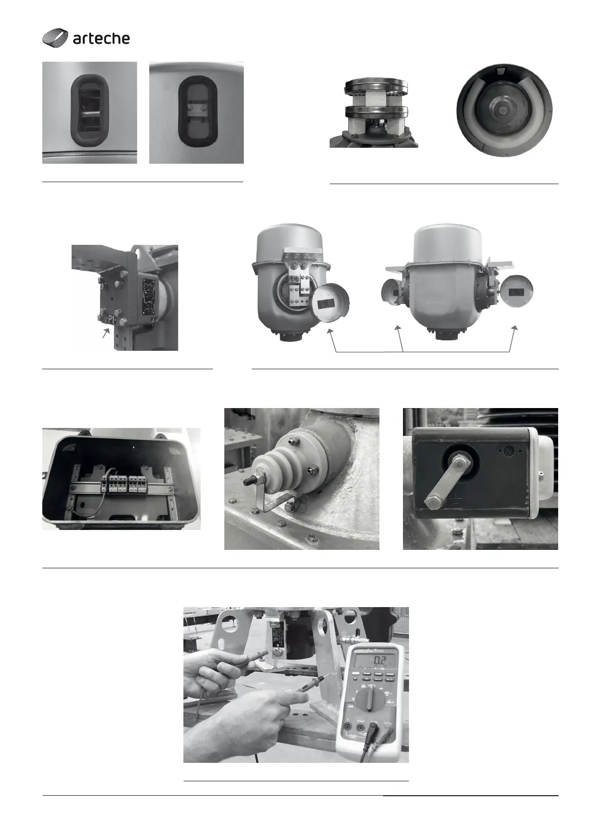
› Fig. 5: Level indicator
› Fig. 6: Oil Compensator Protection
› Fig. 10: Resistance measurement tgδ tap connection
› Fig. 8: Primary diagram plate under the protective cover
› Fig. 7: Primary diagram plate next to the terminal
› Fig. 9: Neutral Grounding