2
High Voltage Instrument Transformers | CA/UT/KA
User Manual - Annex III
The purpose of this test is to assess the insulation of the HV
transformer.
The IEC 61869-1 standard labels this test as a special test,
and mentions that “the test circuit must be agreed between
the manufacturer and the customer”, and that “the dielectric
dissipation factor depends on the insulation design.” The usual
values are less than 0.5%.
There is no mention of this test in the IEEE C57.13 standard.
NOTE: Field testing of tanδ may be susceptible to di erences
in measured values from factory testing due to the following
factors:
› The type of test equipment used and the measurement voltage
level.
› Thermal conditions (high humidity, rain, pollution).
› Temperature of the test object.
› Induced voltages to the test object through other equipment.
It is recommended that the surfaces of the transformer (insulators
and others) be clean, to avoid external leakage currents.
The fi eld measurement of tanδ for transformers that are
already equipped with capacitive test taps (tanδ tap) can be
carried out in the same manner as at the factory. In the case
of other instrument transformers without tanδ tap, the base of
the instrument transformer is always grounded and cannot be
isolated. Therefore, it is possible that the measurement of tanδ
that is carried out in the factory or in the laboratory cannot be
carried out in the substation in the same manner.
Test instruments for fi eld use are usually equipped with solutions
to compensate for external leakage current. The voltage test
for this particular equipment is typically 10 kV for high voltage
insulation and approximately 2.5 kV for low voltage insulation.
Ta n δ and capacitance measurement can also be performed in
the fi eld using other low voltage test bridges and a transportable
high voltage test set capable of measuring voltages up to the
nominal voltage. The choice and application of various test
equipment is at the discretion and experience of the user.
In addition to the measurement of tanδ, the measuring
equipment can usually also measure other parameters such as
capacitance and power factor.
MEASUREMENT OF CAPACITANCE AND DIELECTRIC DISSIPATION FACTOR (tan
δ
)
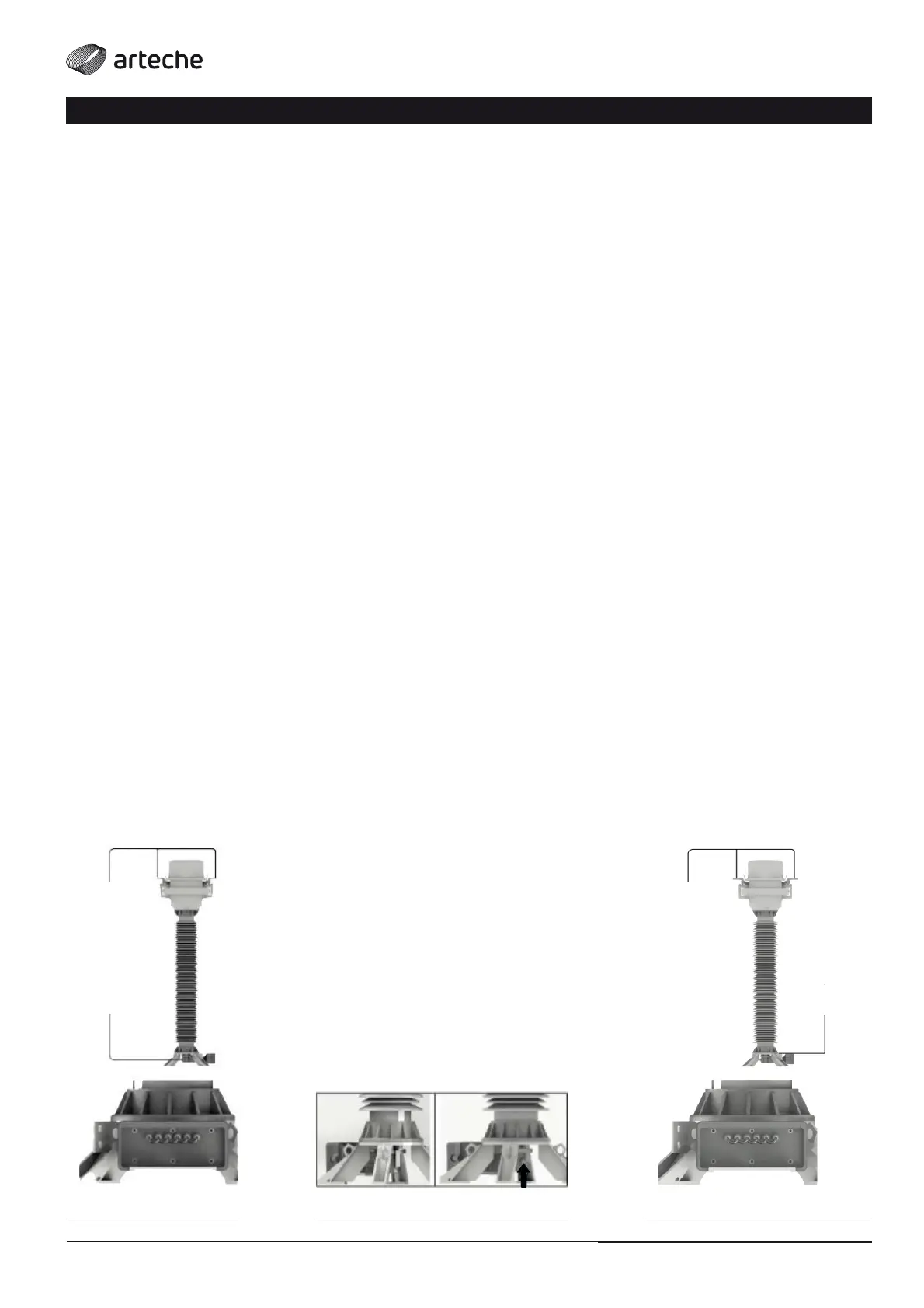
› Fig. 1a
POWER
SUPPLY
ELECTRODE
10 kV
MEASUREMENT
ELECTRODE
› Fig. 1b › Fig. 2
MEASUREMENT
ELECTRODE
POWER
SUPPLY
ELECTRODE
10 kV
It is recommended that the test be carried out at a voltage of
10 kV AC.
If the device has a tanδ tap, it is recommended to perform the
test through this tap.
› HV (UST) test for transformers with tanδ tap (Fig. 1):
• The test must be performed in UST (Ungrounded Specimen
Test) mode.
• The power supply cable (HV) of the measuring equipment
must be connected to the primary terminals P1 and P2, which
are short-circuited with each other.
• The measurement cable must be connected to the tanδ tap,
which should be previously disconnected from the ground
(Fig. 1b).
• The secondary terminals must be short-circuited and grounded.
• Warning: At the end of the test, tanδ tap must be connected
to earth and its contact verifi ed.
› HV (GST) test for transformers without tanδ tap (Fig. 2):
• The test must be performed in GST ( Ground Specimen Test)
mode.
• The power supply cable (HV) of the measuring equipment
must be connected to the primary terminals P1 and P2, which
are short-circuited with each other.
• The measuring cable of the measuring instrument must be
connected to the ground terminal, directly at the base of the
instrument.
• The secondary terminals must be short-circuited and
grounded.
CURRENT TRANSFORMERS/