2
High Voltage Instrument Transformers | CA/UT/KA
User Manual
FOREWORD/
This manual describes the construction, installation, commissioning and monitoring for safe use of a high-voltage instrument
transformer with oil-paper insulation.
INTRODUCTION
SCOPE OF APPLICATION/
The manual applies to the following transformers:
› Current Transformers, CA Series, Models: CA-36..800.
› Inductive Voltage Transformers, UT Series, Models UTx-52..525.
› Combined Transformers, KA Series, Models KA-36..245.
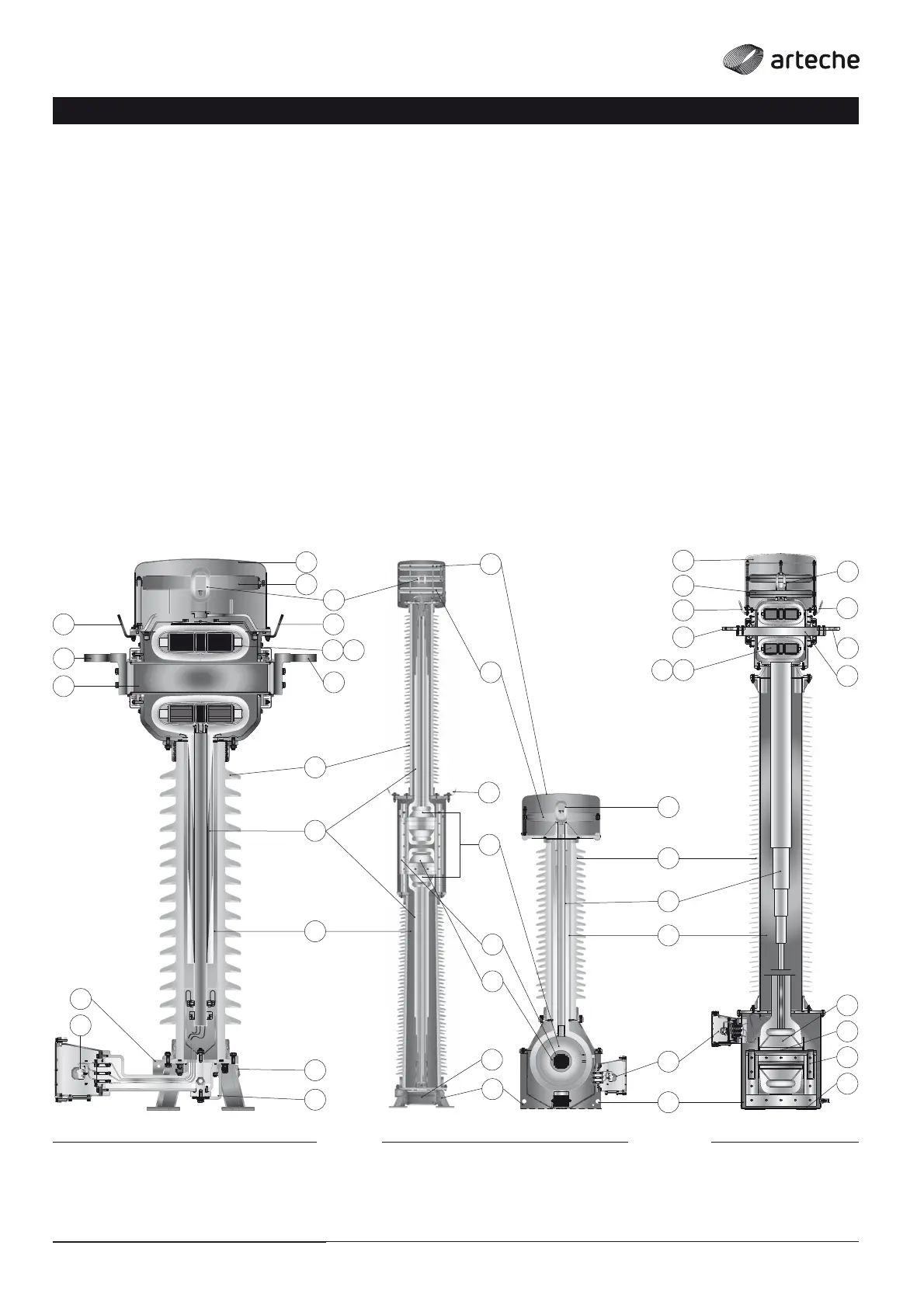
DESIGN/
Instrument transformers have the active parts located inside
a metal enclosure located in the upper part for current
transformers and in the lower part for voltage transformers.
The insulator can be either ceramic (porcelain) or polymeric
(silicone), and is composed of a certain number of sheds.
The internal insulation consists of layers of paper impregnated
with dielectric oil, with a relatively small volume, and hermetically
sealed.
The variations in oil volume are balanced by one or more stainless
steel compensators located in the device’s upper enclosure. A
highly visible indicator at the top shows the compensator position.
At the bottom of the transformer there is a valve for oil sampling.
The secondary terminals of the windings are located in the
terminal box at the base of the transformer.
All metal parts are treated against rust and the fasteners are
made of stainless steel.
1. Cover
2. Oil volume compensator
3. Primary terminal
4. Core(s)
5. Primary winding
6. Secondary winding
7. Insulator
8. Capacitive bushing
9. Insulating oil
10. Secondary terminals
11. Tan Delta measurement tap
12. Ground terminal
13. Oil level indicator
14. Eyebolts for lifting
› CA › KA› UTx
1
3
5
7
8
9
10
12
11
2
3
1
2
3
3
4
1
2
4
4 6
6
5
5
6
7
8
9
10
13
10
12
12
13
4
5
6
13
14
14 14
14
14
14
14