3
High Voltage Instrument Transformers | CA/UT/KA
User Manual - Annex III
It is recommended that the test be carried out at a voltage of
10 kV AC.
If the device has a tanδ tap, it is recommended to perform the
test through this tap.
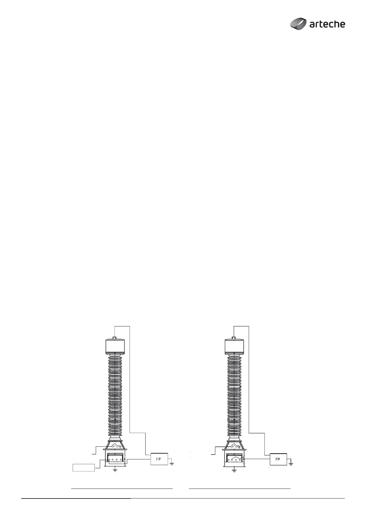
› HV (UST) test for transformers with tanδ tap (Fig. 3):
• The test must be performed in UST (Ungrounded Specimen
Test) mode.
• The (HV) power cable of the measuring equipment must be
connected to the primary terminal (A).
• The neutral connection of the primary (N*) must be
disconnected from the ground and connected to the guard
cable.
• The measurement cable must be connected to the tanδ tap,
which should be previously disconnected from the ground.
• The corresponding secondary terminals at the end of each
secondary winding must be connected to each other, and to
earth.
• Warning: At the end of the test, the tanδ should be grounded
and the contact should be verifi ed.
› HV (GST) test for transformers without tanδ tap (Fig. 4):
• The test must be performed in GST ( Ground Specimen Test)
mode.
• The (HV) power cable of the measuring equipment must be
connected to the primary terminal (A).
• The neutral connection of the primary (N*) must be
disconnected from the ground and connected to the guard
cable.
• The measuring cable of the measuring instrument must be
connected to the ground terminal, directly at the base of the
instrument.
• The corresponding secondary terminals at the end of each
secondary winding must be connected to each other, and to
earth.
INDUCTIVE VOLTAGE TRANSFORMERS/
› Fig. 3
A
Ta n δ tap
LV
measuring
cable
› Fig. 4
A
* The N or P2 terminal can be located inside the secondary terminal box on the side of the box or on the outside of the tank.
N N
LV
measuring
cable
Guard
Wire - P2
Guard
Wire - P2