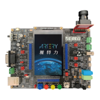
Feature
Core: ARM
®
32-bit Cortex
®
-M4F CPU with FPU
− 288 MHz maximum frequency, with a Memory
Protection Unit (MPU), single-cycle multiplication
and hardware division
− Floating Point Unit (FPU)
− DSP instructions
Memories
− 256 to 4032 KBytes of Flash memory
− sLib: configurable part of main Flash set as a library
area with code executable but secured, non-
readable
− 384 to 512 KBytes of SRAM
− External memory controller (XMC) with 16-bit data
bus: supports CF, SRAM, PSRAM, NOR, NAND,
SDRAM memories
− Up to 2 x QSPI interfaces for external SPI Flash or
SPI RAM extension, and memory mapping mode
LCD parallel interface, 8080/6800 modes
Power control (PWC)
− 2.6 V ~ 3.6 V application supply
− Power-on reset (POR)/ low-voltage reset (LVR), and
power voltage monitor (PVM)
− Low power: Sleep, Deepsleep, and Standby modes
− VBAT supply for LEXT, ERTC and 20 x 32-bit battery
power register (ERTC_BPR)
Clock and reset management (CRM)
− 4 to 25 MHz crystal oscillator (HEXT)
− Internal 48 MHz factory-trimmed clock (HICK),
accuracy 1% at T
A
=25 °C, 2.5 % at T
A
=-40 to
+105 °C, with automatic clock calibration (ACC)
− PLL with configurable frequency multiplication and
division factor
− 32.768 kHz crystal oscillator (LEXT)
− Internal 40 kHz RC oscillator (LICK)
Analog
− 3 x 12-bit 5.33 MSPS A/D converters, up to 24 input
channels, 12-bit/10-bit/8-bit/6-bit configurable
resolution
− Temperature sensor (V
TS
), internal reference
voltage (V
INTR
), V
BAT
battery voltage monitor
(V
BAT
/4)
− 2 x 12-bit D/A converters
DMA:
− 2 x general-purpose DMAs and 1 x EDMA
− 22 channels in all
Up to 116 Fast I/O Interfaces
− All mappable to 16 external interrupt vectors
− Almost 5 V-tolerant
Up to 18 Timers (TMR)
− Up to 13 x 16-bit timers + 2 x 32-bit timers, each with 4
IC/OC/PWM or pulse counter channels
− 2 x Watchdog timers (WDT and WWDT)
− SysTick timer: 24-bit downcounter
ERTC: enhanced RTC with auto wakeup, alarm,
subsecond precision, hardware calendar and
calibration feature
Up to 23 communication interfaces
− Up to 3 x I
2
C interfaces (SMBus/PMBus)
− Up to 4 x USARTs/4 x UARTs (ISO7816 interface, LIN,
IrDA capability, modem control and RS485 drive enable,
with interchangeable TX/RX)
− Up to 4 x SPIs (36 Mbit/s), all with I
2
S interface
multiplexed, I
2
S2/ I
2
S3 support full-duplex
− Up to 2 x CAN interfaces (2.0B Active)
− Up to 2 x OTG FS controllers supporting crystal-less
− Up to 2 x SDIO interfaces
− Infrared transmitter (IRTMR)
− 10/100M Ethernet MAC with dedicated DMA and
SRAM(4 Kbytes): IEEE1588 hardware support, MII/RMII
available (For AT32F437 only)
8~14 bit parallel digital camera interface (DVP)
CRC Calculation Unit
96-bit ID (UID)
Debug mode
− SWD and JTAG interfaces
Temperature range: -40 to 105℃
Packaging
− LQFP144 20 x 20 mm LQFP100 14 x 14 mm
− LQFP64 10 x 10 mm LQFP48 7 x 7 mm
− QFN48 6 x 6 mm
List of Models

 Loading...