MX-2406M / MX-5006M
6
REMOTE MIC
MIC 1MIC 2
MIC 3
MIC 4
SIREN
MIC
LINE
PHANTOM
MIC
LINE
PHANTOM
MIC
LINE
PHANTOM
MIC
LINE
PHANTOM
CHIME
TEL
EMC
MUTE
G
+
G
+
TEL
FM ANT
G
+
SIREN
CHIME
XLR BAL
1-GND
2-HOT+
3-COLD-
COM
BATT SUPPLY
24V
8A
OUTPUT
100V
70V
COM
4-16Ω
OUT IN
LINE LINE2
IN
LINE1
ZONE
1
COM
100V
ZONE
2
ZONE
3
ZONE
4
ZONE
5
ZONE
6
COM COM COM COM COM
100V 100V 100V 100V 100V
1
2 3 4
5
6
7
8 9
101112141617
1315
OUTPUT
100V
70V
COM
4-16Ω
4~16Ω
70V LINE
OUTPUT
100V
70V
COM
4-16Ω
100V LINE
OUTPUT
100V
70V
COM
4-16Ω
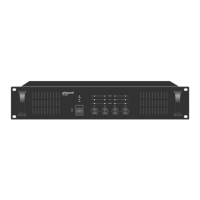
Total impedance
20
(MX-2406M)
9.8
(MX-5006M)
Total impedance
41
(MX-2406M)
20
(MX-5006M)
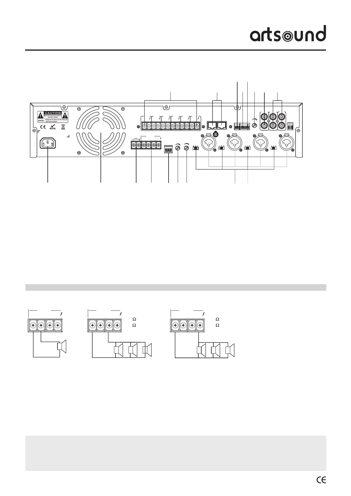
1. AC power supply
2. Ventilation grid
3. 24V DC power supply (backup)
4. 4~16Ω/70V/100V speaker clamps
COM = speaker mass
70V/100V = speaker “+” terminal
4~16Ω = terminal for speakers 4~16Ω
5. Alarm/Siren trigger
6. Siren volume control
7. Alarm volume control
8. Selection button LINE/MIC/phantom power
9. MIC1/MIC2/MIC3/MIC4 balanced input
10. RCA line signal input
11. RCA line signal output
12. Tel. input volume control
13. Tel. signal input
14. EMC input
15. MUTE input
16. MIC-216 (selective calling console) input
17. 6-zone 100V speaker output
4.3 Rear panel.
WARNING
Makesuretoattachtheincludedcoveraftercompletingtheconnection.
Nevertouchthespeakerterminalstopreventelectricshock.
Donotinstallthisamplierinasmallroomwithinsufcientventilation.
• Make sure the equipment is switched off before
connecting the speakers. When the equipment is
switched on, there is a risk of electric shock.
• It is not possible to use the 4 ~ 16Ω/70V/100V
terminals simultaneously.
• Makesurethespeakerwiresarenotstrained.
• During installation of the speakers, make sure the sum
of nominal input power of the speakers to be connected
is lower than the nominal power of the equipment.
5. Use.
5.1 Connectthespeakers