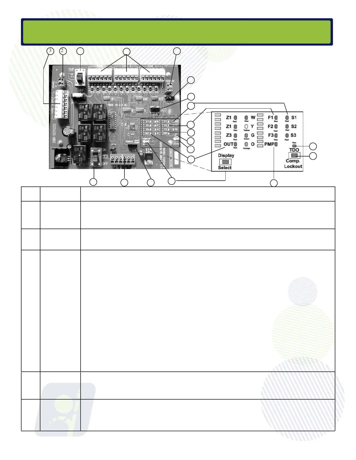
# Name Description
1 PWR On/
Off w/LED
The Arzel
®
System is powered by a 40 VA 24VAC transformer (provided). This switch and the
HVAC system equipment power switch must always be in the “OFF” position when connecting wires
to any terminals
2 24VAC
Terminals
The Arzel
®
40 VA transformer (provided) must be connected to these two terminals.
3 HVAC
Output
Terminals
Output to the HVAC equipment is controlled by a set of Dry-Contact Relays. The HVAC “R” signal
is turned around and sent out to start the appropriate equipment when called by the Zone Control.
The HVAC Output circuit is therefore completely isolated from the Zone Control and thermostat
power supply.
R.
W.
Y.
G.
O/
B.
C.
Connect hot or + side of HVAC equipment transformer (24 VAC) to this
terminal.
Connect to W1 of furnace. (Aux. heat terminal if heat pump is installed.)
Connect to compressor contactor.
Connect to equipment fan relay.
Connect either “O” or “B” to heat pump reversing valve, as required by
heat pump manufacturer. Use the “O” signal if the unit reverses in the
cooling cycle; the “B” if it reverses in the heating cycle.
Connect common side of HVAC equipment transformer (24 VAC) to this
terminal.
4
Thermostat
Terminals
Connect thermostat wires (R,W,Y,G,O, and C) as required for your application.
Note which thermostats are connected to which zones. (24VAC)
5
ODT
Terminals
1
23
4
5
6
9
15
16
11
10
14
7
8
12
13
17
LED Display Inset
10
11
12
Board Layout
Emergency Heat Changeover terminals (2.9-3.3VDC) “Remote ODT” are used with an outdoor
thermostat to run the emergency heat for dual fuel applications. Do not connect “W” from the zone
thermostats to the Arzel MPS board if using the MPS in a duel fuel application. Set thermostats as
“Heat Pump without Aux” so that only Y-G are energized on a call for heating.
7