11
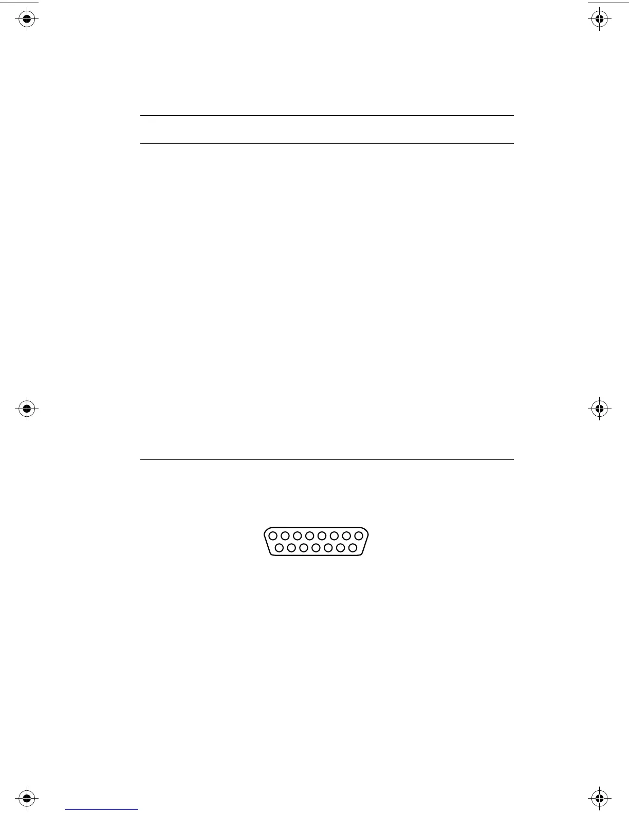
AUI Connector Pin-Outs
Table 3 AUI connector pin-outs
Figure 7 AUI connector pin number assignment
Pin Circuit Signal name
03
10
11
DO+
DO–
DO S
Data Out + (transmit pair)
Data Out –
Data Out Shield
05
12
04
DI+
DI–
DI S
Data In + (transmit pair)
Data In –
Data In Shield
07
15
08
CO+
CO–
COS
Control Out + (optional)
Control Out –
Control Out Shield
02
09
01
CI+
CI–
CI S
Control In + (optional)
Control In –
Control In shield
06
13
14
VC
VP
VS
Voltage Common (power pair)
Voltage Plus
Voltage Shield
Shell PG Protective Ground
8
15
7654321
14 13 12 11 10 9
friendlynet BOOK Page 11 Thursday, October 16, 1997 10:37 AM