SECTION 3 TESTING & SERVICE
3--1
PREVENTIVE MAINTENANCE
Reasonable care in preventive maintenance will insure
high reliability and long life for the automatic transfer
switch.
Operate the switch at least once a month.Performthis
four step Electrical Operation Test. This is a test with
load transfer.
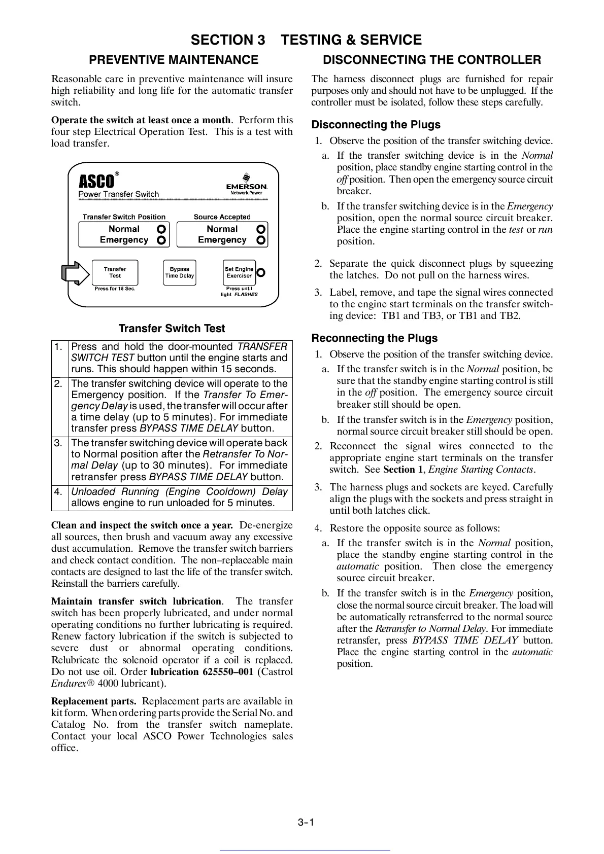
Transfer Switch Test
1. Press and hold the door-mounted TRANSFER
SWITCH TEST button until the engine starts and
runs. This should happen within 15 seconds.
2. The transfer s witching device will operate to the
Emergency position. If the Tr ans fer To Em er-
gencyDelay is used, the transfer will occur after
a t ime delay (up to 5 minutes). For immediate
transfer press BYPASS TIME DELAY button.
3. The transfer switching device w ill operate back
to Normal position after the Retransfer To Nor-
mal Delay (u p t o 30 minutes). For immediate
retransfer press BYPASS TIME DELAY button.
4. Unloaded Running (Engine Cooldown) Delay
allows engine to run unloaded for 5 minutes.
Clean and inspect the switch once a year. De-energize
all sources, then brush and vacuum away any excessive
dust accumulation. Remove the transfer switch barriers
and check contact condition. The non–replaceable main
contacts are designed to last the life of the transfer switch.
Reinstall the barr iers careful l y.
Maintain transfer switch lubrication.Thetransfer
switch has been properly lubricated, and under normal
operating conditions no further lubricating is required.
Renew factory lubrication i f the switch is subjected to
severe dust or abnormal operating conditions.
Relub r icate the sol en o id oper ator if a co il is repl aced.
Do not use oil. Order lubrication 625550–001 (Castrol
EndurexR 4000 lubricant).
Replacement parts. Replacement parts are available in
kit form. When ordering parts provide the Serial No. and
Catalog No. from the transfer switch nameplate.
Contact your local ASCO Power Technologies sales
office.
DISCONNECTING THE CONTROLLER
The harness disconnect plugs are furnished for repair
purposes only and should not have to be unplugg ed. If the
controller must be isolated, follow these steps carefully.
Disconnecting the Plugs
1. Ob serve the position of the transfer switching device.
a. If the transfer switching device is in the Normal
position, place standb y engine starting control in the
off position. Then open the emergency source circuit
breaker.
b. If the transfer switching device is in the Emergency
position, open the normal source circuit breaker.
Place the engi ne starting control in the test or run
position.
2. Separate the quick disconnect plugs by squeezing
the latches. Do not pull on the harness wires.
3. Label, remove, and tape the signal wires connected
to the engine start terminals on the transfer switch-
ing device: TB1 and TB3, or TB1 and TB2.
Reconnecting the Plugs
1. Ob serve the position of the transfer switching device.
a. If the transfer switch is in the Normal position, be
sure that the standby engine starting control i s still
in the off position. The emergency source circuit
breaker still should be open.
b. If the transfer swi tch is in the Emergency position,
normal source circuit breaker still should be open.
2. Reconnect the signal wires connected to the
appropriate engine start terminals on the transfer
switch. See Section 1, Engine Starting Contacts .
3. The harness plugs and sockets are keyed. Care fully
align the plugs with the sockets and press straight in
until both latches click.
4. Restore the opposite source a s follows:
a. If the transfer switch is in the Normal position,
place the standby engine starting control in the
automatic position. Then close the emergency
source circuit breaker.
b. IfthetransferswitchisintheEmergency position,
close the normal source circuit breaker. The load will
be automatically retransferred to the normal source
after the R etr a nsf e r to Norm a l Delay. For immediate
retransfer, press BYPASS TIME DELAY button.
Place the engine starting control in the automatic
position.
Get other manuals https://www.bkmanuals.com

 Loading...


