Page 5 of
7
©ASCO, L.P. 160 Park Avenue, Florham Park, New Jersey 07932 www.asco.com
I&M No
V 9629 R9
All Ri
hts Rese
ved
2.5 SIL
Capability
2.5.1 Systematic
Integrity
The product has met manufacturer design process requirements of Safety Integrity Level (SIL) 3. These
are
intended to achieve sufficient integrity against systematic errors of design by the manufacturer. A
Safety
Instrumented Function (SIF) designed with this product must not be used at a SIL level higher than
the
statement without “prior use” justification by end user or diverse technology redundancy in the
design.
2.5.2 Random
Integrity
The solenoid valve is a Type A Device. Therefore when used the only component in a final
element
subassembly, a design can meet SIL 3 @ HFT=1 and SIL 2 @
HFT=0.
When the final element assembly consists of many components (solenoid valve, quick exhaust valve,
actuator,
isolation valve, etc.) the SIL must be verified for the entire assembly using failure rates from all
components.
This analysis must account for any hardware fault tolerance and architecture
constraints.
3 Installation and
Commissioning
3.1
Installation
•
The ASCO Solenoid valve must be installed per standard installation practices outlined in
the
Installation
Manual.
•
The environment must be checked to verify that environmental conditions do not exceed the
ratings.
•
The ASCO Solenoid must be accessible for physical
inspection.
•
Instrument Air Filtration: These solenoids are intended for use on clean, dry air or inert gas filtered
to
50 microns or better. To prevent freezing, the dew point of the media should be at least
18
°
F
(10
°
C)
below the minimum temperature to which any portion of the clean air or gas system could be
exposed.
Instrument air in compliance with ANSI/ISA Standard S7.3-1975 (R1981) exceeds the
above
requirements and is, therefore, an acceptable medium for these
valves.
•
It is the operator’s responsibility to only use design options such as latches, when it is safe to do so.
•
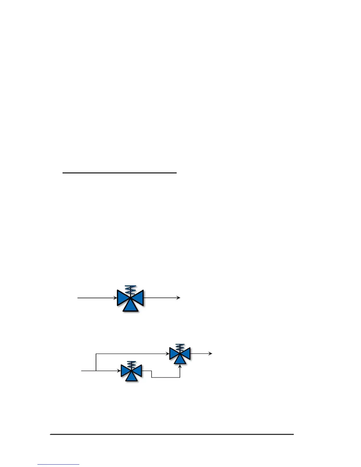
Typical 3-way pilot valve piping
configurations:
a. 1 out-of 1 – This is the most common pilot valve configuration
used.
b. 2 out-of 2 – This is commonly used for high availability applications. In the case that
one
solenoid valve was to spuriously trip, the second solenoid still maintains the position of
the
actuator/process valve at its operating state. Both solenoids must close in order to shift
the
actuator/process valve to its non-operating
state.
 Loading...