ASCO 917 & 918 Owner’s Manual
4
Table F – Accessory 47, 48, 49 module numbers
Module
Control
Voltage
2–Wire Control
Accessory
47 Modules
3–Wire Control
Accessory
48 Modules
Form 3 Control
Accessory
49 Modules
120 V
ac
429447–001 429448–001 429449–001
24 V
ac & dc
429447–002 429448–002 429449–002
240/277
Vac
429447–003 429448–003 429449–003
12 V
ac & dc
429447–004 429448–004 429449–004
Table G – Connections to Control Modules
Module Terminal
Connect To
1 not used
2 control station for Acc. 48, 49
3 control station for Acc. 47, 48, 49
4 module control voltage*
5 RC switch control voltage
O pre–connected to O on RC switch
C pre–connected to C on RC switch
* F or dc control modules connect terminal 4 to negative (–).
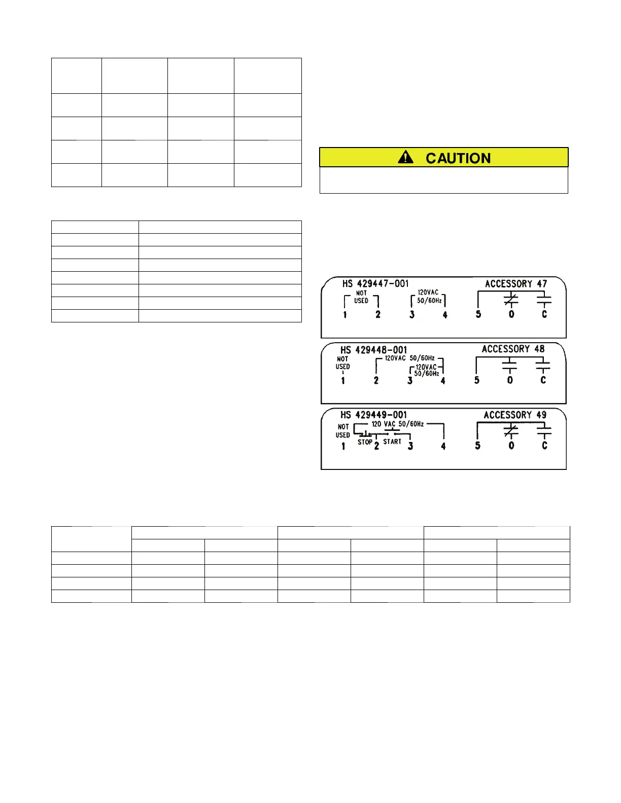
Connections
Connections to the Accessory 47, 48, and 49 control
modules are shown in Table G. Also refer to the labels in
Figure 1 and to Wiring Diagram 363165 or 383880.
Barrier screw type terminals accept #22–12 AWG Cu
control wiring. Tighten terminals to 12 inch–pounds.
The control modules have t wo colored leads
pre–connected to the O and C terminal bus on the RC
switch. A yellow wire runs between the O terminals; and
orange/black wire runs between the C terminals.
Connect your control wiring for the module to terminals
2, 3,and4 on the modules. Terminal 2 is not used on
Accessory 47 and terminal 1 is never used.
For dc modules be sure to
connect terminal 4 to negative (–).
Connect your control wiring for the R C switch (coil
voltage) to terminal 5 on the control module and
terminal L on the RC switch. If the line voltage (service)
isthesameasthecoilvoltage,thecontrolvoltagecan
come di rectly from the poles of the RC switch.
Figure 1. Typical labels on control modules.
Table H – Rating for Cont r ol Modules
Acc. 47 Acc. 48 Acc. 49
on
ro
o
u
e
AC DC AC DC AC DC
120 V ac 1.90 — 1.60 — 3.70 —
24 V ac & dc 0.85 0.36 0.34 0.38 0.70 0.72
240 / 277 V ac 4.00 — 2.50 — 6.00 —
12 V ac & dc 0.60 0.32 0.34 0.36 0.68 0.70