ASCO 917 & 918 Owner’s Manual
5
!
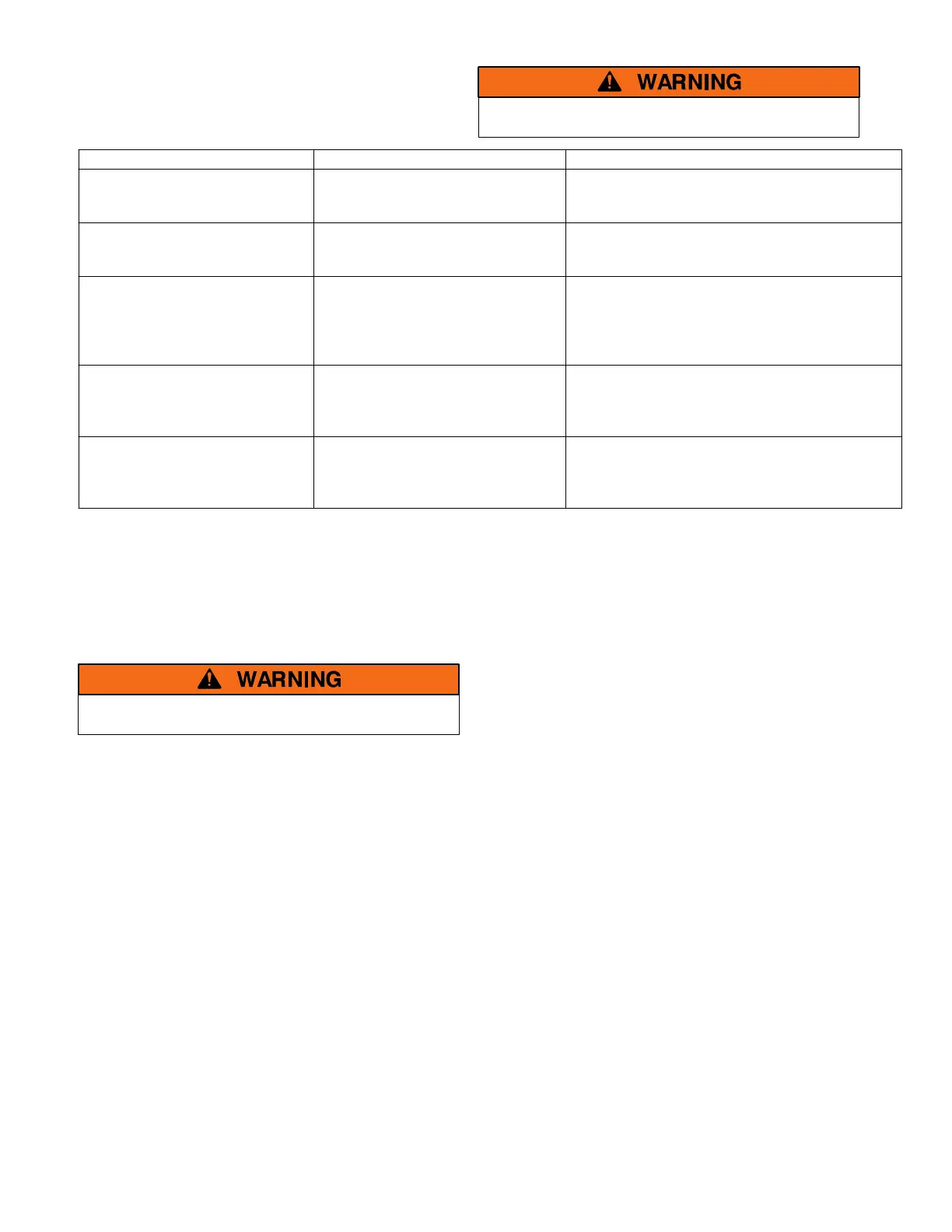
Trouble–Shooting
The RC switc h is energized. Proceed with care!
Problem
Check Control Voltage Check Control Station, Wiring, Supply
RC switch does not close when
control station is closed.
Measure control voltage between
RC switch terminals L and C.
If no voltage is present, check control station
contacts, control wiring, supply fuses, and
optional accessories.
RC switch does not close when
control station is opened.
Measure control voltage between
RC switch terminals L and O.
If no voltage is present, check control station
contacts, control wiring, supply fuses, and
optional accessories.
RC switch tries to open or
close, but cannot.
Measure at least 90% control
voltage (nameplate coil voltage)
between RC switch terminals L
and C, or L and O.
Ifvoltageislow,checkcontrolwiresizeand
line run distance; see Table D on page 5. If a
transformer is used in the control line, make
sure it can handle the VA burden required;
see Table E on page 5.
RC switch closes and opens
repeatedly.
—
Check control station for overlapping
contacts, and correct. Control station cannot
call on RC switch to close and open at the
same time.
RC switch closes or opens very
quickly with excessive noise.
Measure no more than 110%
control voltage (nameplate coil
voltage) between RC switch
terminals L and C, or L and O.
If voltage is high, change control supply or
change RC switch.
Manual Operation
A #8–32 screw 1 1/2 inches long can be used to manually
operate the RC switch. One is supplied in all
replacement parts kits that require manual operation.
The screw should be used for maintenance purposes
only. Remove the screw after maintence.
Do not manually operate the RC switch until all
power and control ci r cuits are disconnected.
Open circuit breakers, then use a voltmeter to verify no
voltage is present at the RC switch at both control and
line terminal screws.
Insert the operating screw into the center of the coil and
carefully turn it clockwise until the threads engage the
cam/core.
Pull the screw outward to open the R C switch contacts;
push it in to close the contacts. Observe the buttons in
the contact block (buttons out means contacts open).
Replacement Parts
The main contact blocks and the operator coil are
available in kit form. When ordering parts, provide the
Serial No. and Catalog No. from the RC switch
nameplate. Contact your local ASCO Authorized
Representative, Sales Office, or ASI.
Included in each kit are instructions that explain how to
replace the parts. These instructions are also available
separately:
Service Bulletin 381339–021
Note: ASCO 918 RC Switches are provided with a coil
circuit specifically designed for HID lighting
applications. Do not disconnect or remove this circuit
component.
Conversion Kits
Conversion kits are available for field or distributor
modification of ASCO 917 and 918 Remote Control
Switches to allow changes in pole configuration, control
voltage, control modules, and auxiliary contacts.

 Loading...


