ASCO 917 & 918 Owner’s Manual
2
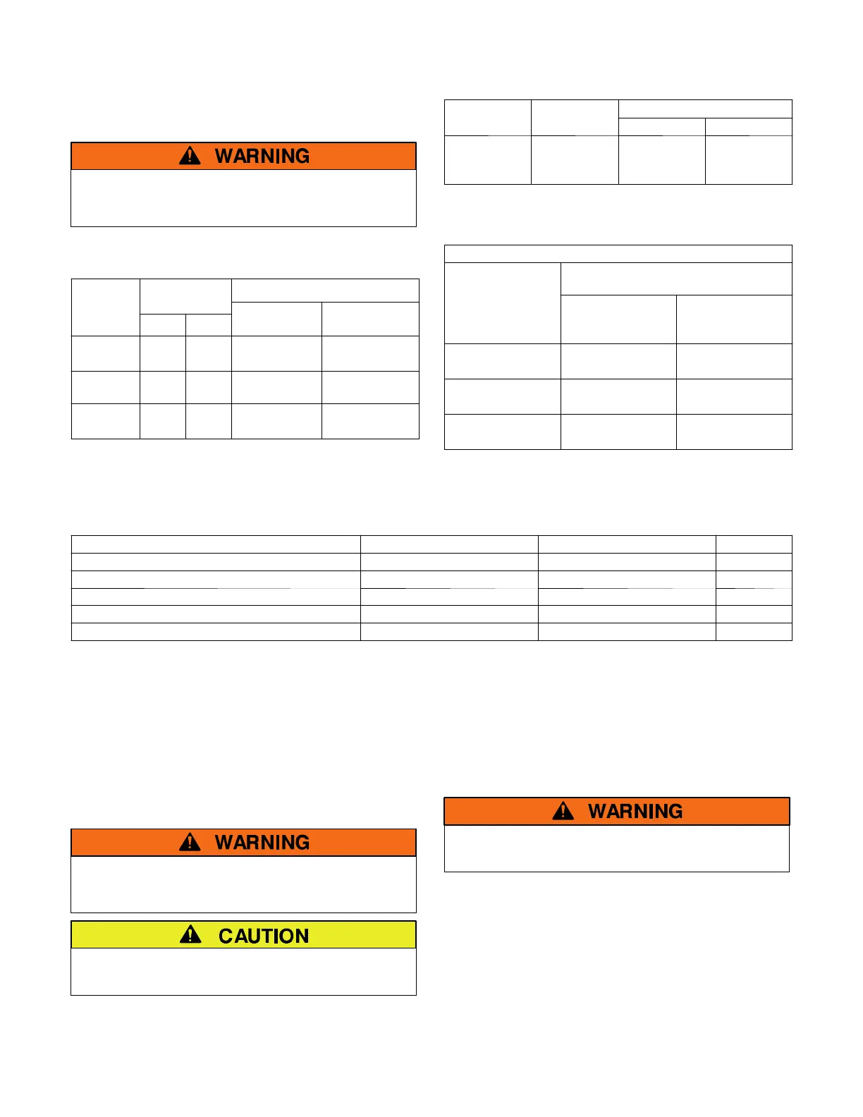
These RC Switches are UL–508 listed and are available
in2to12polesinglethrowdoublebreakand2to6pole
normally open and normally closed configurations.
Control voltages are from 120 to 480 V ac. See tables A,
B, and C for contact ratings.
Do not exceed these values. Exceeding the
rating can cause personal injury or serious
equipment damage.
Table A – Maximum AC V oltage and Current Ratings
for ASCO 917 & 918 Main Contacts (open or closed)
Amperes
Poles to Load
Continuous
Type
917 918
1phase
3
or 3 phase
General 30 30 347 V ac 600 V ac
Standard
Ballast*
20 30** 347 V ac 600 V ac
Tungsten 20 20 250 V ac 250 V ac
Table B – Maximum DC Voltage and Current Ratings
for ASCO 917 & 918 Main Contacts (open or closed)
m
eres
Poles to Load
oa
ype
Continuous
2inSeries 3inSeries
General 20 125 V dc 250 V dc
Table C – Withstand Current Ratings
for ASCO 917 & 918 Remote Control Swi tc he s
Available Symmetrical Amperes RMS
When Used w ith
Molded–Case Circuit Breakers
t
Service Voltage
Withstand
Current Rating
(amperes)
Maximum
Breaker Size
(amperes)
250 V 22,000 30
480 V 14,000 30
600 V 10,000 30
* ASCO 918 is preferred for HID and metal halide loads.
** 20 A Standard Ballast Rating for ASCO 918 N/O & N/C.
Drawing Index
Drawing Description Standard RC Switch N/O & N/C RC Switch Page
RC Switch Outline & Mounting 361069 383826 6
Outline & Mounting with Accessories 363164 383897 7&8
Wiring Diagram 361068 383825 9
Wiring Diagram with Accessories 363165 383880 10 & 11
Enclosure Outline & Mounting 363104 363104 12
Installation
ASCO 917 & 918 Remote Control (RC) Switches are
pre–tested and ready to use. Installation requires
mounting and connection of service cables and control
circuit wires. An experienced licensed electrician should
install the RC Switch.
Each RC Switch has a ratings / identification label
defining load types and maximum voltage ratings. Use
theswitchonlywithinthelimitsshownonthislabel.
Do not exceed the values on the rating label.
Exceeding the rating can cause personal injury
or serious equipment damage.
To preven t malfunct ion or short en e d life, prote c t
the switch from construction grit and metal chips.
Mounting: Five Outline and Mounting Diagrams are
furnished. Select the appropriate diagram and mount the
RC Switch. All mounting details and instructions are
shownonthediagrams.
The RC switch can be mounted in any position but is
usually mounted vertically. Mounting holes in open–type
RC Switches accept #10 screws (3/8–inch minimum
length). Enclosure mounting holes accept 1/4–inch
diameter screws.
Line and Load Connections
Deenergize the branch circuit to be connected
to the RC Switch and the control line too.
Four Wiring Diagrams arefurnished.Lineandload
terminals are reversible. The RC switch is UL listed for
use with 60 or 75 degrees C cable. All power wires
should enter enclosure adjacent to the RC switch
terminals. Combination knockouts are provided on
NEMA Type 1 enclosures. Line and load connectio ns are
supplied with clamp–type terminals. These terminals
accept the wire sizes #18–10 AWG Cu. Insert appropri-
ate line and load wires and tighten clamp screws to 18
inch–pounds.
 Loading...


