TD 91684GB
16 April 2015 / Ver. G
Installation Guide
T942C and T942C/2 Central Unit
15
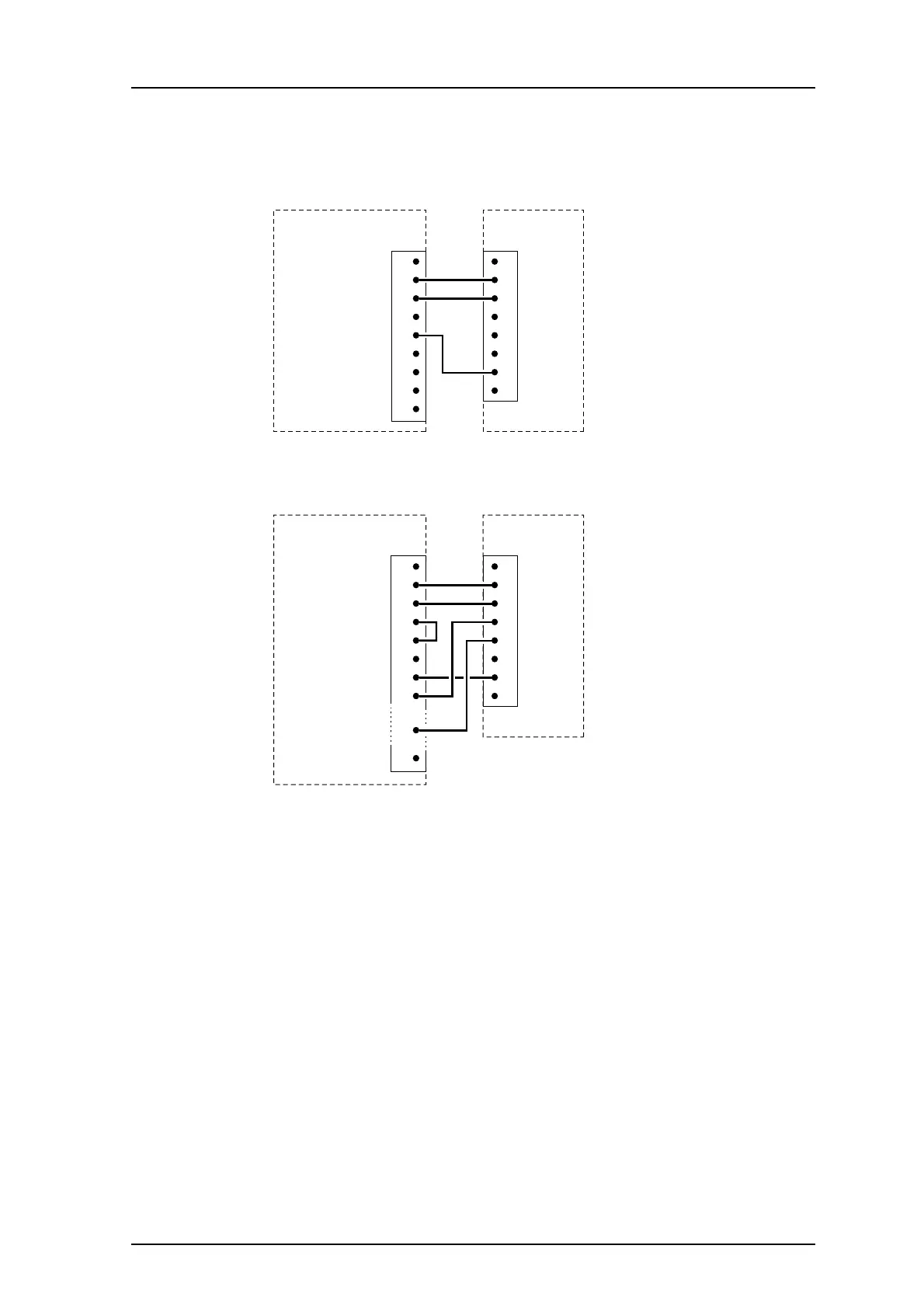
1.4.10 Connection of PC
The serial communication port on the PC is to be
connected to 8-pin modular connector J09
on the T942C, either directly or via modems. (See the drawings below.)
1 (not used)
2 TX
3 RX
4 (not used)
5 (not used)
6 (not used)
J09
7 GND
8 (not used)
1
RX 2
TX 3
4
GND 5
6
7
8
9
T942C
9-pin female
D-sub connector
for direct
connection
to PC
Figure 18. 9-pin modular connector.
1 (not used)
2 TX
3 RX
4 CTRL IN
5 CTRL OUT
6 (not used)
J09
7 GND
8 (not used)
1
TX 2
RX 3
RTS 4
CTS 5
6
25-pin male
D-sub connector
for connection
to PC via
modem
GND 7
DCD 8
DTR 20
T942C
25
Figure 19. 25-pin modular connector.
NOTE: Note that on modems with 25-pin D-sub connectors, th
e RTS and CTS signals must be
jumpered - i.e. pin 4 to 5.
Adapters with the correct connections can be ordered from
Ascom for both the 9-pin and
25-pin D-sub connectors.