TD 91684GB
16 April 2015 / Ver. G
Installation Guide
T942C and T942C/2 Central Unit
23
2.4.5 Connection of Buses
Buses are connected either via modular bus cabling or twiste
d-pairs.
NOTE: Data buses are polarized! Use only twisted-pai
rs for separate wiring!
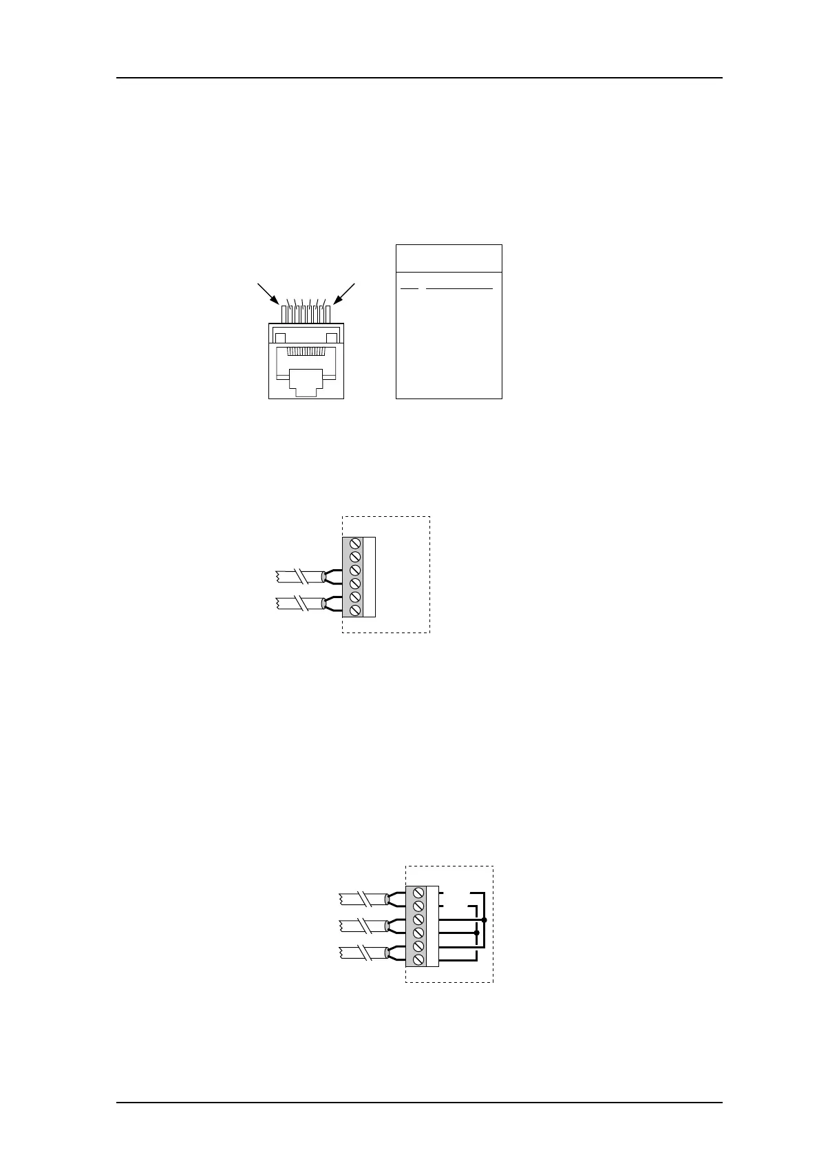
Bus Connections via Modular Bus Cabling
Pin
1
2
3
4
5
6
7
8
Signal
A1
A2
-
-
D1
D2
SP1
SP2
J01 + J02
Pin 1
234567
Pin 8
Figure 27. Modular bus cable pins.
• Connect the modular bus cabling to connector
s J01 and J02.
Bus Connections via twisted-pairs
Figure 28. Twisted-pairs connection.
• A-bus to J04 screw 3 and 4
• D-bus to J04 screw 5 and 6
2.4.6 Connection of Supply Voltage
1 Add the FP5 Fuse board 1.25A, a very-fast actin
g (FF) fuse, to the circuit board, in
between connector J03 and the screw terminal.
2 Connect supply voltage to connector J03 sc
rew 1 and 2. See also the System
Installation document, under Power Supply.
J03
4
5
6
3
1 +12V
2 GND
Supply voltage in
Supply voltage out
to other units
Figure 29. Power supply connection.