Ascon Tecnologic - K32 Line - ENGINEERING MANUAL - PAG. 2
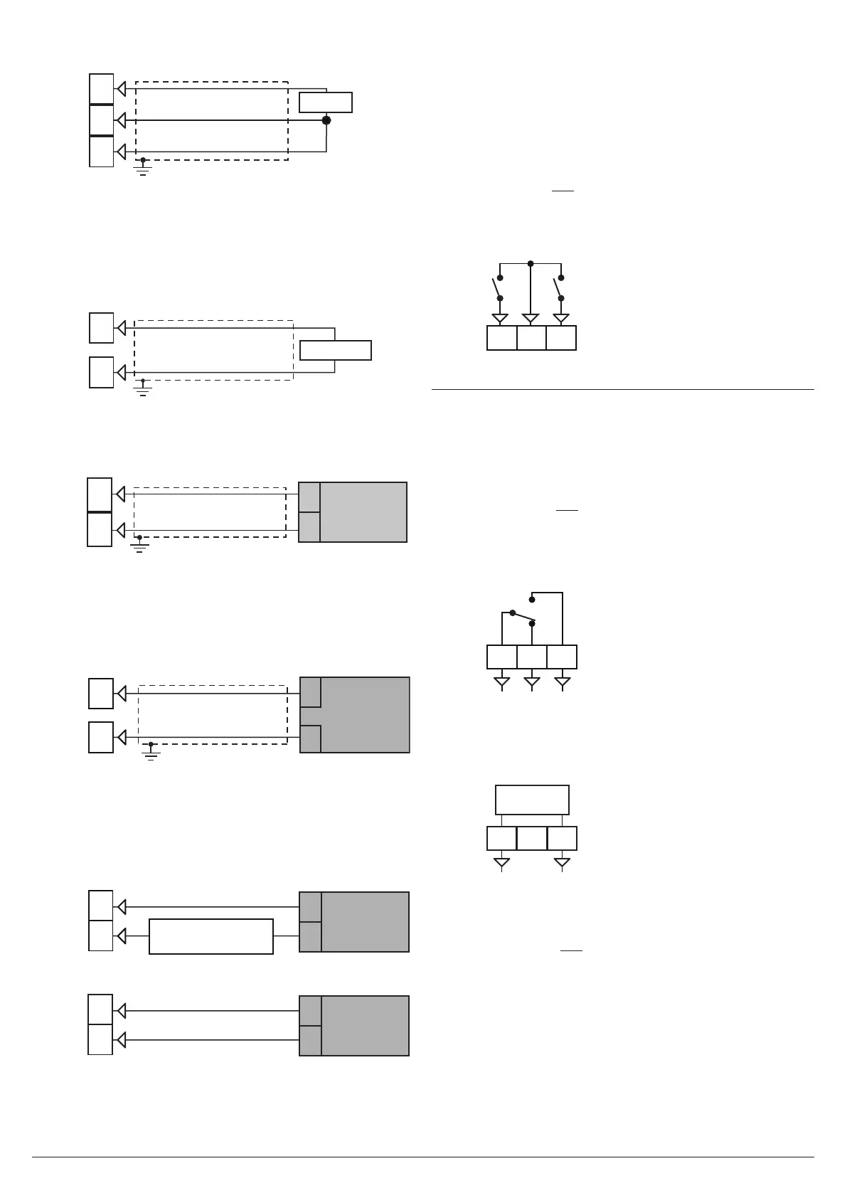
2.2.3 RTD (Pt 100) Input
3
RTD
1
2
Input circuit: Current injection (135 µA).
Line resistance: Automatic compensation up to 20Ω/wire
with maximum error ±0.1% of the input span.
Calibration: According to EN 60751/A2.
Note: The resistance of the 3 wires must be the same.
2.2.4 Thermistors Input
3
PTC/NTC
1
Input circuit: Current injection (25 µA).
Line resistance: Not compensated.
2.2.5 V and mV Input
mV
V
+
__
2
1
+
Input impedance: > 1 MΩ
Accuracy: ±0.5% of Span or ±1 dgt @ 25°C.
2.2.6 mA Input
0/4... 20 mA input wiring for passive transmitter
using the auxiliary pws
+
_
+
_
4... 20 mA
2 wires
transmitter
4
1
Input impedance: < 51Ω.
Accuracy: ±0.5% of Span or ±1 dgt @ 25°C.
Protection: NOT protected from short circuit.
Internal auxiliary PWS: 10 VDC (±10%), 20 mA max..
0/4... 20 mA input wiring for passive transmitter
using an external pws
+
_
+
_
1
2
0/4...20 mA
Passive
transmitter
_
External
PWS
+
0/4... 20 mA input wiring for active transmitter
1
2
0/4...20 mA
Active
transmitter
-
+
-
+
2.2.7 Logic Inputs
Safety notes:
• Do not run logic input wiring together with power cables;
• Use an external dry contact capable to switch 0.5 mA, 5 VDC;
• The instrument needs 150 ms to recognize a contact
status variation;
• Logic inputs are not isolated by the measuring input.
A double or reinforced isolation between logic inputs and
power line must be assured by the external elements.
Logic input driven by dry contact
Digital
Input 1
7
65
Digital
Input 2
2.3 Outputs
Safety notes:
• To avoid electrical shocks, connect power line at last.
• For supply connections use No. 16 AWG or larger wires
rated for at last 75°C.
• Use copper conductors only.
• SSR outputs are not isolated. A reinforced isolation must
be assured by the external solid state relays.
2.3.1 Output 1 (OUT1)
Relay Output
NONCC
24
2322
Contact rating: •8A/250Vcosj =1
•4A/250Vcosj =0.4
Operation: 1 x 10
5
SSR Output
SSR
24
2322
+-
Logic level 0: Vout < 0.5 VDC;
Logic level 1: •12V±20%@1mA;
•10V±20%@20mA.
Note: This output is not isolated. A double or reinforced
isolation between instrument output and power supply
must be assured by the external solid state relay.