Ascon Tecnologic - KM3 - L - ENGINEERING MANUAL - PAG. 2
20 minutes.
Input impedance: > 1 M!.
Burn out: full scale
Calibration: According to EN 60584-1.
Note: For TC wiring use proper compensating cable
preferable shielded.
2.2.2 RTD Pt 100 Input
Input circuit: Current injection (135 µA).
Line resistance: Automatic compensation up to 20!/wire
with maximum error ±0.03% of the input span.
Calibration: According to EN 60751/A2.
Note: The resistance of the 3 wires must be the same.
2.2.3 RTD Pt 1000 Input
Line resistance: Not compensated.
Pt 1000 input circuit: Current injection (15 µA).
Pt 1000 calibration: According to EN 60751/A2.
2.2.4 V and mV Input
Input impedance: > 1 M! for mV Input
500 k! for Volt Input.
2.2.5 mA Input
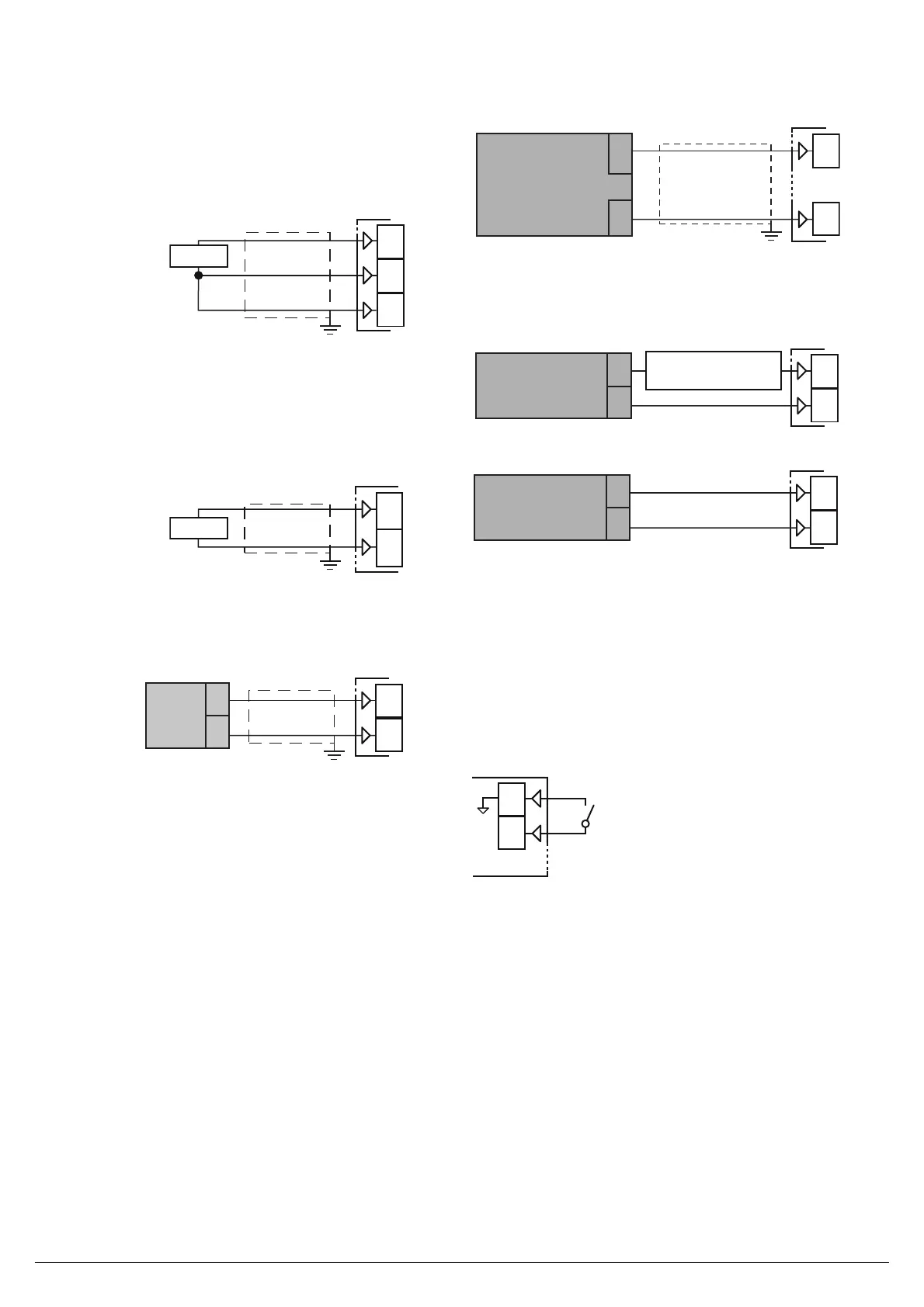
0/4 to 20 mA input wiring for passive transmitter
using the auxiliary pws
+
_
4 to 20 mA
Passive
transmitter
4
1
Input impedance: < 53!.
Internal auxiliary PWS: 12 VDC (±10%), 20 mA max..
0/4 to 20 mA input wiring for passive transmitter
using an external pws
+
_
+
_
1
2
0/4 to 20 mA
Passive
transmitter
_
External
PWS
+
0/4 to 20 mA input wiring for active transmitter
0/4 to 20 mA
Active
transmitter
+
_
+
_
1
2
2.2.6 Logic Inputs
Safety notes:
– Do not run logic input wiring together with power cables;
– The instrument needs 150 ms to recognize a contact
status variation;
– Logic inputs are NOT isolated by the measuring input.
A double or reinforced isolation between logic inputs and
power line must be assured by the external elements.
Logic inputs driven by dry contact
Maximum contact resistance: 100!.
Contact rating: DI1 = 10 V, 6 mA;
2.3 OUTPUTS
Safety notes:
– To avoid electrical shocks, connect power line at last.
– For supply connections use No. 16 AWG or larger wires
rated for at last 75°C.
– Use copper conductors only.
– SSR outputs are not isolated. A reinforced isolation must
be assured by the external solid state relays.
– For SSR, mA and V outputs if the line length is longer than
30 m use a shielded wire.
– Do not short-circuit the terminals of the SSR output.
WARNING! Before connecting the output actuators,
we recommend to con" gure the parameters to