ASCON TECNOLOGIC - TLK33 - OPERATING INSTRUCTIONS - PAG. 10
37
SELF
Selftuning enable no / yES no
38
Pb
Prop
ortional band 0 ÷ 9999 50
39
Int
In
tegral time OFF ÷ 9999
sec.
200
40
dEr
De
rivative time OFF÷ 9999
sec.
50
41
FuOc
Fuzzy overshoot control
0.00 ÷ 2.00 0,5
42
tcr1
Cy
cle time of HEATING
output
0.1 ÷ 130.0
sec.
0.1
43
Prat
Pow
er ratio Cooling /
Heating
0.01 ÷ 99.99 1.00
44
tcr2
Cy
cle time of
COOLING output
0.1 ÷ 130.0
sec.
0.1
45
rS
Ma
nual reset -100.0÷100.0
%
0.0
46
SLor
Gradient of first ramp:
In
F= Ramp not active
0.00 ÷ 99.99
/ InF
unit/min.
InF
47
dur.t
Duration time between
tw
o ramps
InF= Time not active
0.00 ÷ 99.59
/ InF
hrs.-min.
InF
48
SLoF
Gradient of second
ram
p:
InF= Ramp not active
0.00 ÷ 99.99
/ InF
unit / min.
InF
Group “
]
PAn” (parameters relative to the user interface)
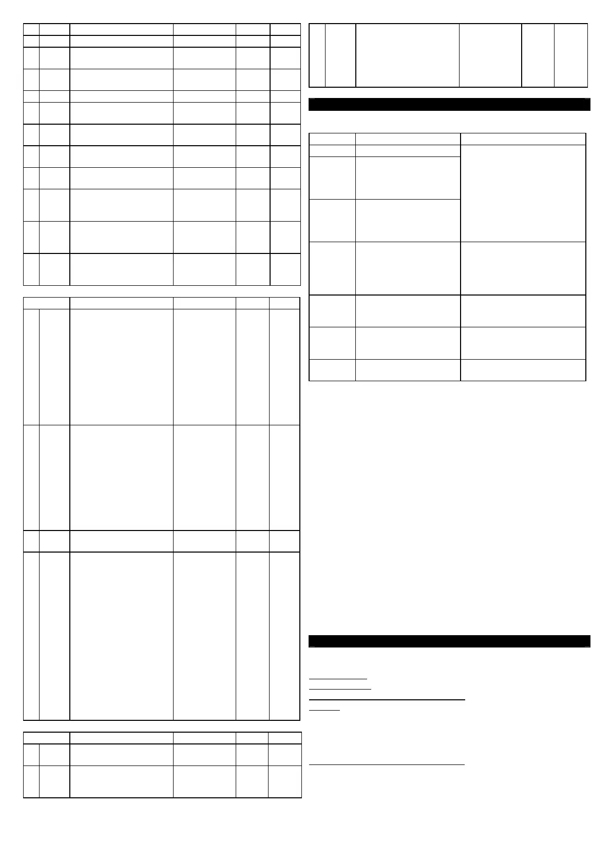
Par. Description Range Def. Note
49
USrb
Functioning of key “U” :
noF = No Function
tu
ne= Start Autotuning
or Selftuning
OPLO= Manual Control
(open loop)
Aac= Reset Alarms
latch
ASi= Aknowledged
Alarms
OFF= Control OFF
noF / tunE /
OPLO / Aac /
ASi / CHSP /
OFF
noF
50
diSP
Variable visualized on
th
e display:
dEF= Process Value
Pou= Control Power
SP.F= Active Set Value
SP.o = Operative Set
va
lue
AL1 = AL1 threshold
AL2 = AL2 threshold
AL3 = AL3 threshold
dEF / Pou /
SP.F / SP.o /
AL1 / AL2 /
AL3
dEF
51
AdE
Shi
ft value for the shift
index functioning
OFF...9999 2
52
Edit
Fa
st progr. Active Set
and alarms:
SE= Active Set can be
modified while the
alarm thresholds
cannot be modified
AE= Active Set cannot
be modified while the
alarm thresholds can
be modified
SAE= Active Set and
alarm thresholds can
be modified
SAnE= Active Set and
alarm thresholds
cannot be modified
SE / AE /
SAE / SAnE
SAE
Group “
]
SEr” (parameters relative to the serial communication)
Par. Description Range Def. Note
53
Add
of serial communication
0 … 255 1
54
baud
(Baud rate)
12
00 / 2400 /
9600 / 19.2 /
38.4
9600
55
PACS
Access at the
pro
gramming through
serial port:
LoCL = No (Local only)
LorE = Yes (Local and
remote progr.)
LoCL / LorE LorE
6 - PROBLEMS, MAINTENANCE AND GUARANTEE
6.1
- ERROR SIGNALLING
Error Reason Action
- - - -
Prob
e interrupted Verify the correct
connection between probe
and instrument and then
verify the correct
functioning of the probe
uuuu
Th
e measured
variable is under the
probe’s limits (under-
range)
oooo
Th
e measured
variable is over the
probe’s limits (over-
range)
ErAt
Aut
o-tuning not
possible because the
process value is too
higher or too lower
Push key “P” in order to
make the error message
disappear. Once the error
has been found, try to
repeat the auto-tuning.
noAt
Aut
o-tuning not
finished within 12
hours
Check the functioning of
probe and actuator and try
to repeat the auto-tuning.
LbA
Lo
op control
interrupted
(Loop break alarm)
Check the working of probe
and actuator and swap the
instrument to (rEG) control
ErEP
Pos
sible anomaly of
the EEPROM memory
Push key “P”
In error conditions, the instrument provides an output power as
programmed on par. “OPE” and activates the desired alarms, if the
relative parameters “ALni” have been programmed = yES.
6.2 - CLEANING
We recommend cleaning of the instrument with a slightly wet cloth
using water and not abrasive cleaners or solvents which may
damage the instrument.
6.3 - WARRANTY AND REPAIRS
The instrument is under warranty against manufacturing flaws or
faulty material, that are found within 18 months from delivery date.
The guarantee is limited to repairs or to the replacement of the
instrument. The eventual opening of the housing, the violation of
the instrument or the improper use and installation of the product
will bring about the immediate withdrawal of the warranty’s effects.
In the event of a faulty instrument, either within the period of
warranty, or further to its expiry, please contact our sales
department to obtain authorisation for sending the instrument to
our company. The faulty product must be shipped to Ascon
Tecnologic with a detailed description of the faults found,
without any fees or charge for Ascon Tecnologic, except in the
event of alternative agreements.
7 - TECHNICAL DATA
7.1
- ELECTRICAL DATA
Power supply: 12...24 VDC +/- 10%
Frequency AC: 50/60 Hz
Power consumption (instrument only): 5 VA approx.
Input/s: 1 input for temperature probes: tc J,K,S ; infrared sensors
ZIS J e K; RTD Pt 100 IEC; PTC KTY 81-121 (990 Ω
@ 25 °C);
NTC 103AT-2 (10KΩ @ 25 °C) or mV signals 0...50 mV, 0...60
mV, 12 ...60 mV or normalized signals 0/4...20 mA, 0..1 V, 0/1...5 V
, 0/2...10 V. 2 digital inputs for free voltage contacts.
Normalized signals input impedance: 0/4..20 mA: 51 Ω; mV and
V: 1 MΩ
 Loading...