ASCON TECNOLOGIC - TLK33 - OPERATING INSTRUCTIONS - PAG. 8
The function of the digital inputs can be set through par. “diF”
contained in the group ““
]
InP”.
The parameter can be programmed as :
= noF : no function
= Aac : Closing the contact connected to the digital input 1 it is
possible to acknowledge the alarm. (see par. 4.5)
= ASi :Closing the contact connected to the digital input 1 it is
possible to acknowledge an active alarm (see par. 4.5)
= HoLd :Closing the contact connected to the digital input 1 there is
the hold of the measure in that instant (P.A.: not the reading on the
display, therefore the indication could settle with a proportional
delay to the filter of measure). With the function hold the instrument
operate the control in base to the memorized measure.
Reopening the contact the instrument come back to the normal
acquisition of the measure.
= OFF :Closing the contact connected to the digital input 1 it is
possible to select the OFF control (OFF).
= CHSP :Closing and opening the contact connected to the digital
input 1 it is possible to select one of the 4 pre-programmed Set
Points on rotation.
= SP1.2 : Closing the contact connected to the digital input 1 it is
possible to select as active the set point SP2. Reopening the
contact is select as active the set point SP1. This function is
possible only when “nSP” = 2, and when is selected it disables the
selection of the active set through the parameter "SPAt" and
through the key U.
= SP1.4 : The following combination of the connected contacts to
the two digital entries allows the activation of one of the 4
memorized set points.
DIG IN1 DIG IN2 SET POINT
off o
ff SP1
on o
ff SP2
off o
n SP3
on o
n SP4
when this function is selected it disables the selection of the active
s
et through the parameter "SPAt" and through the key U.
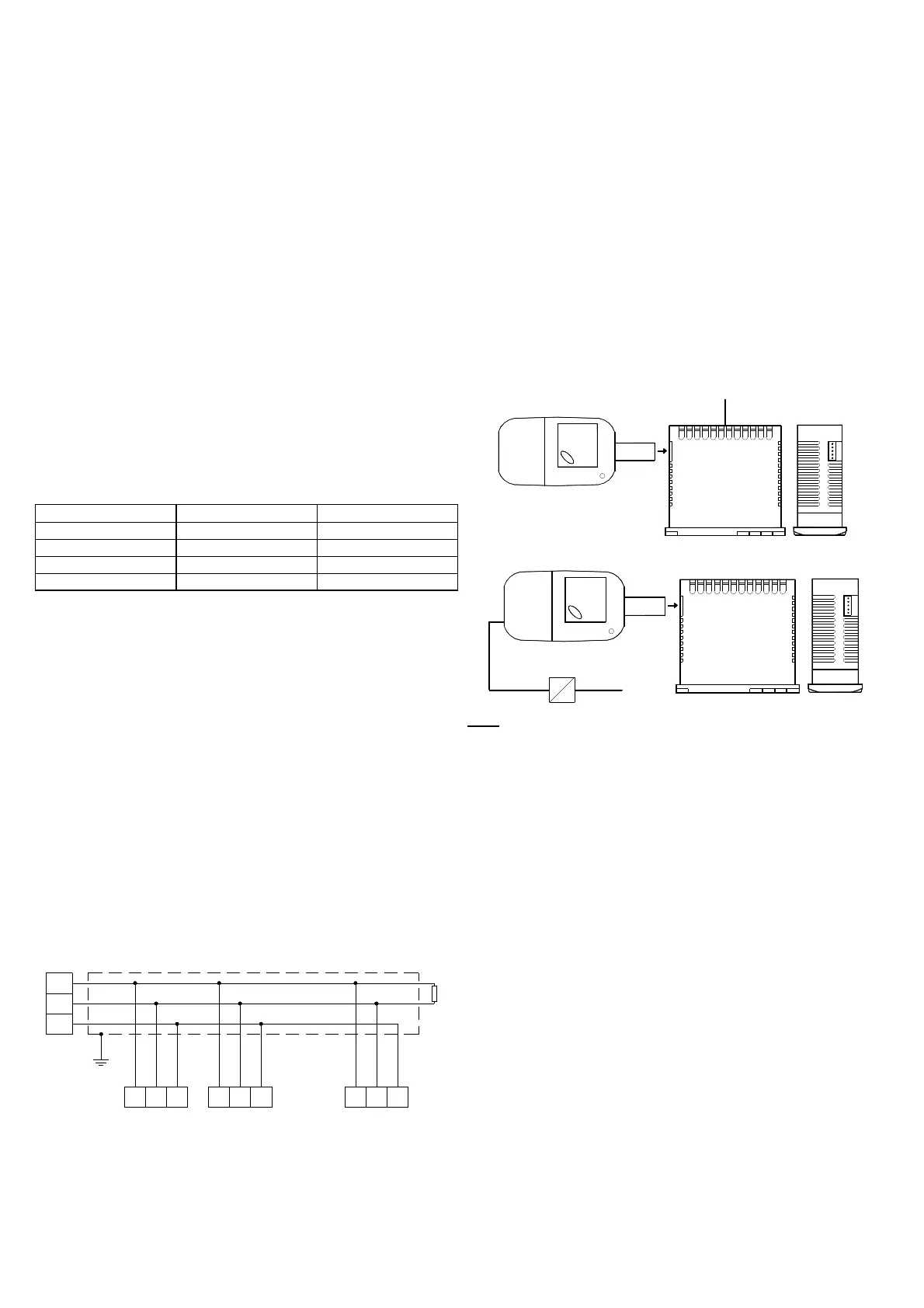
4.8 - RS 485 SERIAL INTERFACE
The instrument can be equipped with a RS 485 serial
communication interface, by means of which it is possible to
connect the regulator with a net to which other instruments
(regulators of PLC) are connected, all depending typically on a
personal computer used as plant supervisor. Using a personal
computer it is possible to acquire all the function information and to
program all the instrument’s configuration parameters. The
software protocol adopted for TLK33 is a MODBUS RTU type,
widely used in several PLC and supervision programs available on
the market (TLK series protocol manual is available on request).
The interface circuit allows the connection of up to 32 instruments
on the same line.
To maintain the line in rest conditions a 120 Ohm resistance (Rt)
must be connected to the end of the line.
The instrument is equipped with two terminals called A and B which
have to be connected with all the namesake terminals of the net.
For the wiring operation it is advisable to adopt a screened cable
wired as in the drawing.
TLK33 n.2TLK33 n.1
10
GND
8
A B
9
A B
TLK33 n.N
GND A GNDB
shield
A
I
nterface
RS485
GND
B
HOST
(
PC/PLC)
120 ohm
R
t
10 8 9 10 8 9
If the instrument is equipped with a serial interface, the parameters
to be programmed are the following, all present in the parameters
group “
]
SEr” :
"Add" : Address of the station. Set a different number for each
station, from 1 to 255.
"baud" : Transmission speed (baud-rate), programmable from
1200 to 38400 baud. All the stations have to have the same
transmission speed.
"PACS" : Programming access. If programmed as "LoCL" this
means that the instrument is only programmable from the
keyboard, if programmed as "LorE" it is programmable both from
the keyboards and serial line.
If an attempt is made to enter the programming from the keyboard
whilst a communication through the serial port is in progress the
instrument will visualise "buSy" to indicate the busy state.
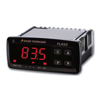
4.9 - PARAMETERS CONFIGURATION BY “A01”
The instrument is equipped with a connector that allows the
transfer from and toward the instrument of the functioning
parameters through the device A01 with 5 poles connector.
This device it’s mainly useable for the serial programming of the
instruments which need to have the same parameters configuration
or to keep a copy of the programming of an instrument and allow its
rapid retransmission.
To use the device A01 it’s necessary that the device or instrument
are being supplied.
Instrument supplied and device not supplied
SUPPLY
In
strument supplied from the device
SUPPLY ADAPTER
1
2 VDC AC SUPPLY
P.
A.: For the instruments equipped with RS485 serial
communication, it’s indispensable that the parameter “PACS” is
p
rogrammed = LorE.
To transfer the configuration of an instrument into the device
(UPLOAD) it is necessary to proceed in the following way:
1) position both dip switch of A01 in the OFF mode.
2) connect the device to the instrument TLK plugging the special
connector.
3) verify that the instrument or the device are supplied
4) observe the indication led on the device A01: if it results green
this means that a configuration is already loaded on the device
while if it results green blinking or red blinking this means that it has
not been loaded any valid configuration on the device .
5) press the button placed on the device.
6) observe the indication led : after having pressed the button, the
led becomes red and therefore, at the end of the data transfer, it
becomes green.
7) now it is possible to disconnect the device.
To transfer the configuration loaded on the device onto an
instrument of the same family (DOWNLOAD), it is necessary to
proceed in the following way:
1) position both dip switch of A01 in the ON mode.
2) connect the device to an instrument TLK having the same
features of the one from which has been downloaded the desired
configuration, plugging the special connector.
3) verify that the instrument or the device are supplied
4) observe the indication led on the device A01: it has to result
green, because if the led results green blinking or red blinking, this
means that on the device it has not been downloaded any valid
configuration and therefore it’s useless to continue.
5) if the les results green, press the button placed on the device.
 Loading...