ASCON TECNOLOGIC - TLK33 - OPERATING INSTRUCTIONS - PAG. 7
With this mode is possible to program the minimum and the
maximum set of “AL1” by “AL1L” and “AL1H” parameters.
LoAb
off
O
N
AL1
AL1
PV
HiAb
HAL1
t
ime
off
ON
A
L1
PV
time
HAL1
off off
O
N
OUT
off off
ON
OUT
AL1
Lo
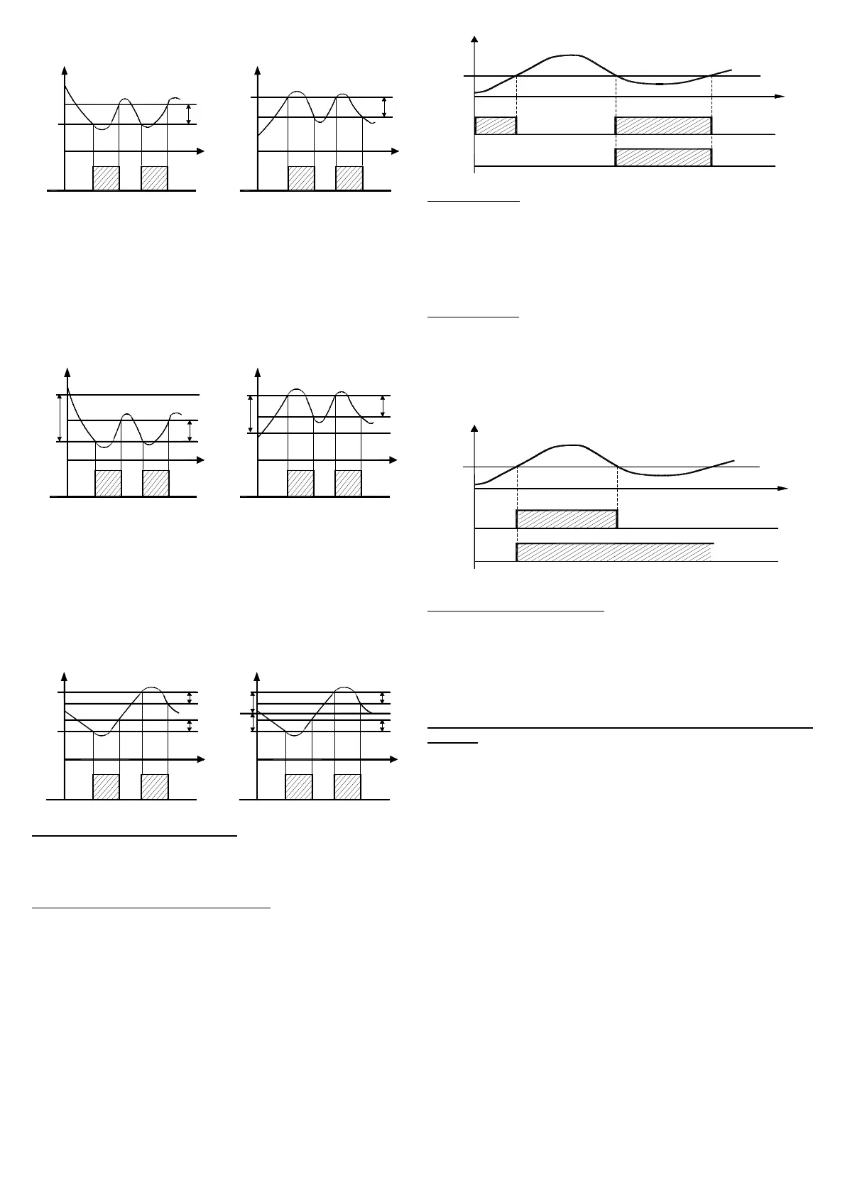
dE = DEVIATION LOW ALARM: The alarm is activated when the
process value goes below the value [SP1 + AL1] and will be
deactivated when it goes above the value [SP1 + AL1 + HAL1].
With this mode is possible to program the minimum and the
maximum set of “AL1” by “AL1L” and “AL1H” parameters.
HidE = DEVIATION HIGH ALARM: The alarm is activated when the
process value goes above the value [SP1 + AL1] and will be
deactivated when it goes below the value [SP1 + AL1 - HAL1].
With this mode is possible to program the minimum and the
maximum set of “AL1” by “AL1L” and “AL1H” parameters.
LodE
ON
off
PV
S
P
-AL1
HAL1
time
off
ON
S
P
AL1
P
V
HidE
time
HAL1
ON
o
ff off
off off
ON
OUT
AL1
OUT
AL1
LH
Ab = ABSOLUTE BAND ALARM: The alarm is activated when
the process value goes under the alarm threshold set on parameter
"AL1L" or goes higher than the alarm threshold set on parameter
"AL1H" and will be deactivated when it goes below the value [AL1H
- HAL1] or when it goes above the value [AL1L + HAL1].
LHdE = DEVIATION BAND ALARM: The alarm is activated when
the process value goes below the value [SP1 + AL1L] or goes
above than the value [SP1 + AL1H] and will be deactivated when it
goes below the value [SP1 + AL1H - HAL1] or when it goes above
the value [SP1 + AL1L + HAL1].
ON
off
AL1H
A
L1L
PV
ON
time
off
HAL1
H
AL1
SP
A
L1L
AL1H
PV
time
HAL1
HAL1
o
ff off
ON
ON
off off
OUT
AL1
OUT
AL1
"Ab
1" - ALARM CONFIGURATION: This parameter can assume a
value between 0 and 15.
T
he number to be set, which will correspond to the function
desired, is obtained by adding the values reported in the following
descriptions :
ALARM BEHAVIOUR AT SWITCH ON: the alarm output may
behave in two different ways, depending on the value added to par.
“Ab
1”.
+0 = NORMAL BEHAVIOUR: The alarm is always activated when
there are alarm conditions.
+1 = ALARM NOT ACTIVATED AT SWITCH ON: If, when switched
on, the instrument is in alarm condition, the alarm is not activated.
It will be activated only when the process value is in non-alarm
conditions and then back in alarm conditions.
P V
+ 1
+
0
t i m e
A
L 1
O N
O N
O N
o
f f o f f
o f fo f f
A b 1
ex
emple with absolute low alarm
ALARM DELAY: the alarm output may behave in two different
ways depending on the value added to par. “Ab1”.
+
0 = ALARM NOT DELAYED: The alarm is immediately activated
when the alarm condition occurs.
+2 = ALARM DELAYED: When the alarm condition occurs, delay
counting begins, as programmed on par. “AL1d” (expressed in
sec.) and the alarm will be activated only after the elapsing of that
time.
ALARM LATCH: : the alarm output may behave in two different
ways depending on the value added to par. “Ab1”.
+
0 = ALARM NOT LATCHED: The alarm remains active in alarm
conditions only.
+ 4 = ALARM LATCHED: The alarm is active in alarm conditions
and remains active even when these conditions no longer exist,
until the correctly programmed key “U”, (“USrb”=Aac) has been
pushed.
A L 1
P V
O N
O
N
t i m e
+ 0
A
b 1
+ 4
o f f
o f f
o f f
ex
emple with absolute high alarm
ALARM AKNOWLEDGEMENT: : the alarm output may behave in
two different ways depending on the value added to par. “Ab1”.
+
0 = ALARM NOT AKNOWLEDGED: The alarm always remains
active in alarm conditions.
+ 8 = ALARM AKNOWLEDGED: The alarm is active in alarm
conditions and can be deactivated by key “U” if properly
programmed (“USrb”=ASi), and also if alarm conditions still exist.
"AL1i" - ALARM ACTIVATION IN CASE OF MEASUREMENT
ERROR:
This allows one to establish how the alarm have behave
in the event of a measurement error (yES=alarm active; no=alarm
d
eactivated).
4.6 - FUNCTIONING OF KEY “U”
The function of key “U” can be set through par. “USrb” contained
in the group ““
]
PAn”.
The parameter can be programmed as :
= noF : no function
= tunE : Pushing the key for 1 sec. at least, it is possible to
activate/deactivate Auto-tuning or Self-tuning
= OPLO : Pushing the key for 1 sec. at least, it is possible to swap
from automatic control (rEG) to manual one (OPLO) and vice versa.
= Aac : Pushing the key for 1 sec. at least, it is possible to
acknowledge the alarm. (see par. 4.5)
= ASi : Pushing the key for 1 sec. at least, it is possible to
acknowledge an active alarm (see par. 4.5)
= CHSP : Pushing the key for 1 sec. at least, it is possible to select
one of the 4 pre-programmed Set Points on rotation.
= OFF : Pushing the key for 1 sec. at least, it is possible to swap
from automatic control (rEG) to OFF control (OFF) and vice versa.
4.7 - DIGITAL INPUTS
The instrument can be equipped with 2 digital inputs.
 Loading...