ASCON TECNOLOGIC - TLK33 - OPERATING INSTRUCTIONS - PAG. 9
6) observe the indication led : after having pressed the button, the
led becomes red and therefore, at the end of the data transfer, it
becomes green.
7) now it is possible to disconnect the device.
For additional info, please have a look at the A01 instruction
manual.
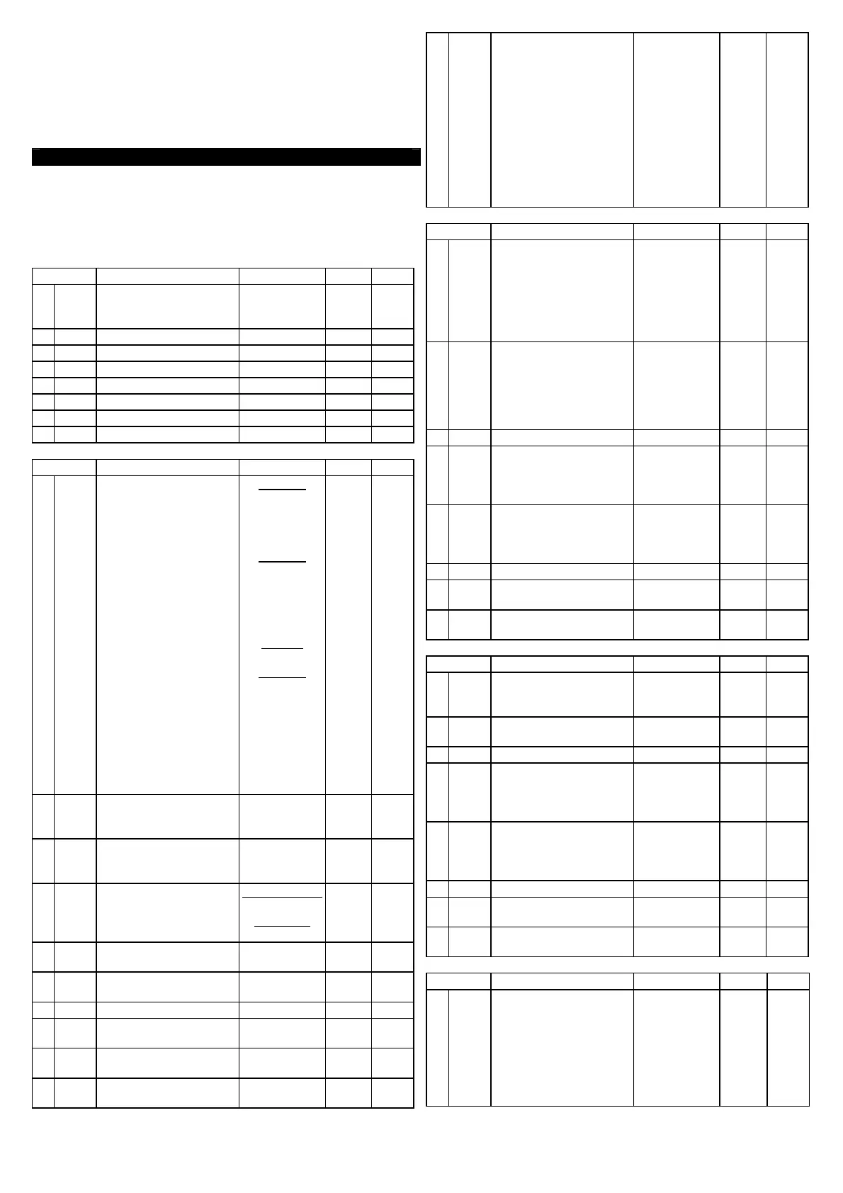
5 - PROGRAMMABLE PARAMETERS TABLE
He
re following are described all the parameters available on the
instrument. Some of them could be not present or because they are
depending on the type of instrument or because they are
automatically disabled as unnecessary
Group “
]
SP” (parameters relative to the Set Point)
Par. Description Range Def. Note
1
n
SP
Number of the
programmable Set
point
1 ÷ 4 1
2
SPA
t
Active Set point 1 ÷ nSP 1
3
SP1
Se
t Point 1 SPLL ÷ SPHL
0
4
SP2
Se
t Point 2 SPLL ÷ SPHL
0
5
SP3
Se
t Point 3 SPLL ÷ SPHL
0
6
SP4
Se
t Point 4 SPLL ÷ SPHL
0
7
SPL
L
Low Set Point -1999 ÷ SPHL -1999
8
SPH
L
High Set Point SPLL ÷ 9999
9999
Group “
]
InP” (parameters relative to the measure input)
Par. Description Range Def. Note
9
SEnS
Probe type:
J
= thermocoupled J
CrAL= termocoupled K
S= thermocoupled S
Ir.J=Infrared Sen. IRS J
Ir.CA= Infrared Sen.
I
RS K
Pt1= thermores. Pt100
0.50= 0..50 mV
0.60= 0..60 mV
12.60= 12..60 mV
Ptc= thermistor PTC
KTY81-121
ntc= thermistor NTC
103-AT2
0.20= 0..20 mA
4.20= 4..20 mA
0.1= 0..1 V
0.5=0..5 V
1.5= 1..5 V
0.10= 0..10 V
2.10= 2..10 V
input D :
J / CrAL / S /
I
r.J / Ir.CA /
Pt1 / 0.50 /
0.60 / 12.60
input E :
J / CrAL / S /
Ir.J / Ir.CA /
Pt
c / ntc /
0.50 / 0.60 /
12.60
input I :
0.20 / 4.20
i
nput V :
0.1 /
0
.5 / 1.5 /
0.10 / 2.10
Pt1
Ptc
4.20
0.10
10
SSC
L
ow scale limit in case
of input with V / I
signals
-1999 ÷ FSC 0
11
FSC
H
igh scale limit in case
of input with V / I
signals
SSC ÷ 9999 0
12
dP
N
umber of decimal
figures
Pt1 / Ptc / ntc:
0 / 1
n
orm sig.:
0 ÷ 3
0
13
Unit
T
emperature unit of
measurement
°C / °F °C
14
FiL
I
nput digital filter 0FF÷ 20.0
sec.
1.0
15
OFSt
Measuring Offset -1999 ÷ 9999 0
16
rot
measuring straight line
0.000 ÷ 2.000
1.000
17
InE
case of measuring error
Our / Or / Ur OUr
18
OPE
measuring error
-1
00 ÷ 100
%
0
19
dIF
D
igital inputs function:
noF = No Function
Aac= Reset Alarms
latch
ASi= Aknowledged
Alarms
HoLd = Hold Measure
OFF= Control OFF
CHSP = Sel. Set Point
SP1.2 = Sel. SP1/SP2
SP1.4 = Sel. SP1,2,3,4
by 2 dig in
noF / AaC /
ASi / HoLd /
SP1.2/ SP1.4
noF
Group “
]
AL1” (parameters relative to alarm AL1)
Par. Description Range Def. Note
20
AL1t
Alarm AL1 type:
L
oAb= Absolute Low
HiAb= Absolute High
LHAb= Absolute Band
LodE= Deviation Low
HidE= Deviation High
LHdE= Deviation Band
LoAb / HiAb
LHAb / LodE
HidE / LHdE
LoAb
21
Ab1
Al
arm AL1 functioning:
power on
+
2 = delayed
+4 = latch
+8 = aknowledged
0 ÷ 15 0
22
AL1
Al
arm AL1 threshold AL1L÷ AL1H
0
23
AL1L
or low alarm
-1
999 ÷ AL1H -1999
24
AL1H
or low alarm
AL
1L ÷ 9999
9999
25
HAL1
Alarm AL1 hysteresis OFF ÷ 9999 1
26
AL1d
Activation delay of
a
larm AL1
OFF ÷ 9999
sec.
OFF
27
AL1i
case of measuring error
no / yES no
Group “
]
AL2” (parameters relative to alarm AL2)
Par. Description Range Def. Note
28
AL2t
Alarm AL2 type:
s
ee “AL1t”
LoAb / HiAb
LHAb / LodE
HidE / LHdE
LoAb
29
Ab2
Al
arm AL2 functioning:
see “Ab1”
0 ÷ 15
0
30
AL2
Al
arm AL2 threshold
AL2L÷ AL2H
0
31
AL2L
or low alarm
-1999 ÷ AL2H -1
999
32
AL2H
or low alarm
AL2L ÷ 9999
9999
33
HAL2
Alarm AL2 hysteresis
OFF ÷ 9999
1
34
AL2d
Activation delay of
a
larm AL2
OFF ÷ 9999
s
ec.
OFF
35
AL2i
case of measuring error
no / yES
no
Group “
]
rEG” (parameters relative to the control)
Par. Description Range Def. Note
36
Auto
Au
totuning Fast enable
OFF = Not active
1 = Start each power on
on
3
= Start manually
4= Start after Soft Start
or change Set Point
O
FF /
1 / 2 / 3 / 4
2