12
3 - Electrical Connections
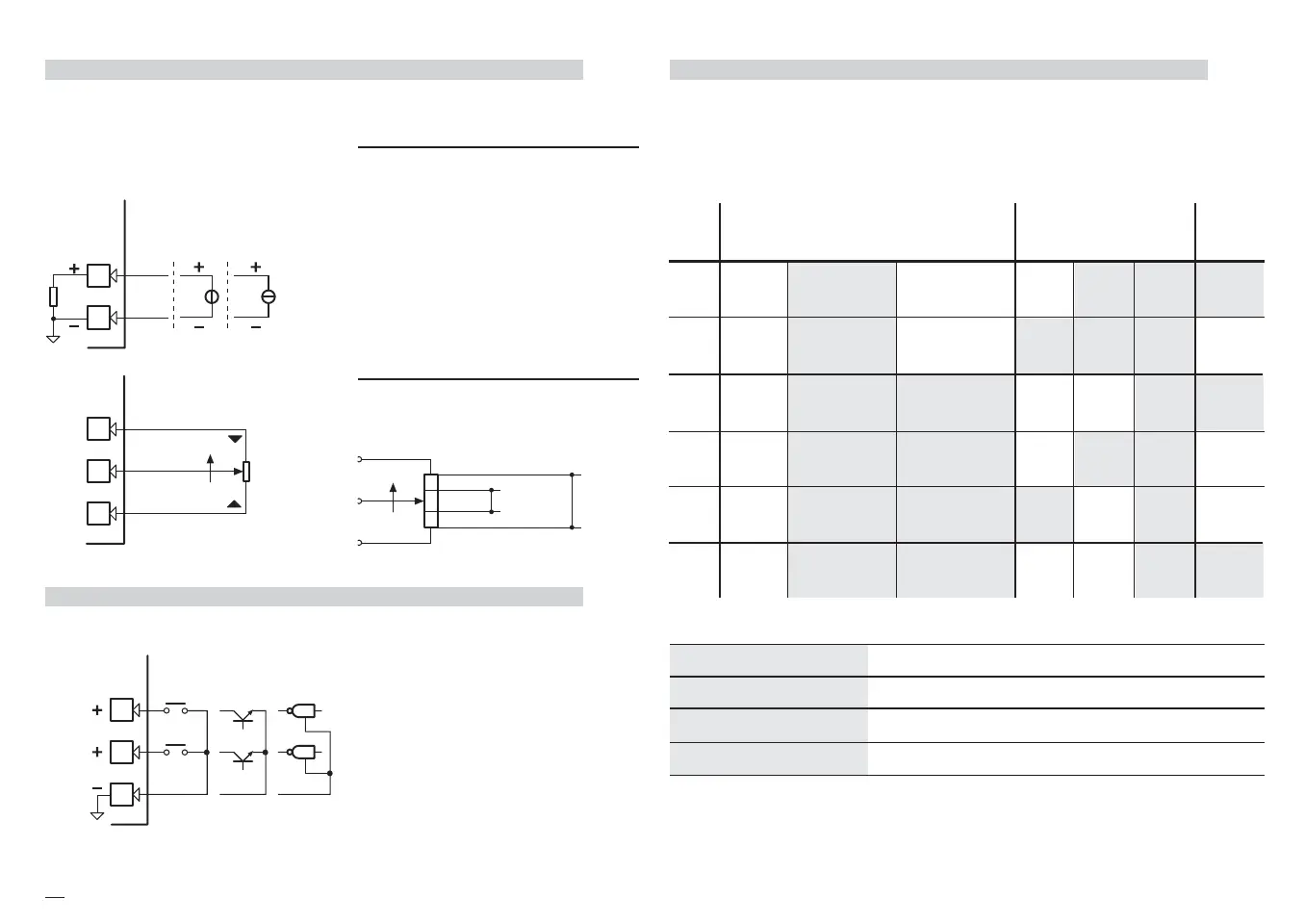
3.3.5 OP1 OP2 OP3 AND OP4 OUTPUTS
B
The functionality associated to each of the OP1 OP2 OP3 and OP4 outputs
is defined during the configuration of the instrument.
The possible choices are:
Note
[1] In case of OP4 analogue output, its status is not visualised by any red led
[2] When the OP4 SSR drive output is selected, the status of OP1 and OP2, as alarms,
is not displayed by any red led
where:
3.3.4 DIGITAL INPUTS
B
• The associated function is active
when the digital input is ON
(see table on page 33)
• The second digital input (IL2) is
available only with the following
options:
Remote Setpoint (D = 2)
Current transformer (D = 3)
SSR drive / analogue output (D = 4)
OP1 - OP2
OP4
Relay or Triac output
Analogue output
Analogue or SSR drive output
OP4-C
9
10
15
TTL
open collector
NPN
open collector
Isolated
contact
Com.
IL 2
IL 1
C1
C2
C From Position Potentiometer
To read the real position of the motor
or the valve
Total
travel
distance
Operating
Travel
distance
pot.h
pot.I
0%
100% From 100Ω to 10KΩ max
3.3.3 AUXILIARY INPUTS (cont.)
B
B From Remote Setpoint
Current
0/4…20mA
Input resistance = 30Ω
Voltage
1…5V, 0…5V, 0…10V
Input resistence = 300KΩ
e If the analogue input is provided, the
terminals for the Remote Setpoint
are 10(+) and 9(-)
OP3
Relay output
Alarms
OP1
Raise
Retransm.
OP1
Heat
OP2 OP3 OP4-C
OP4
Heat
OP1 OP2 OP3
OP1
Heat
OP2
Cool
OP3 OP4-C
OP1
Heat
OP4 [1]
Cool
OP2
[2]
OP3
OP4 [1]
Heat
OP2
Cool
OP1
[2]
OP3
PV-SP
OP2
Lower
OP3 OP4-C
Valve
Double
action
Double
action
Double
action
Single
action
Single
action
Control
6
5
4
3
2
1
M5 UK•ed4 10-12-2004 16:20 Pagina 12

 Loading...

