11
M6 x 40
Cup Head Bolt
TAP IN
WITH HAMMER
M6 X 16
Washer
M6 X 16 Washer
M6 X 16
Washer
M6 x 65 Cup Head Bolt
M6 Hex Nut
M6 Nylock
Nut
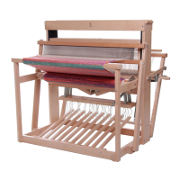
17. Remove the wooden spacer P from the castle E to allow
the warp roller Z to fit between the uprights without
twisting them. Then place the warp roller between the
back uprights C and CX by locating the shaft of the
warp roller into the nylon bush in CX. Secure the warp
roller by tapping a 5/8 x 75 Steel Shaft through the
nylon bush in C and into Z.
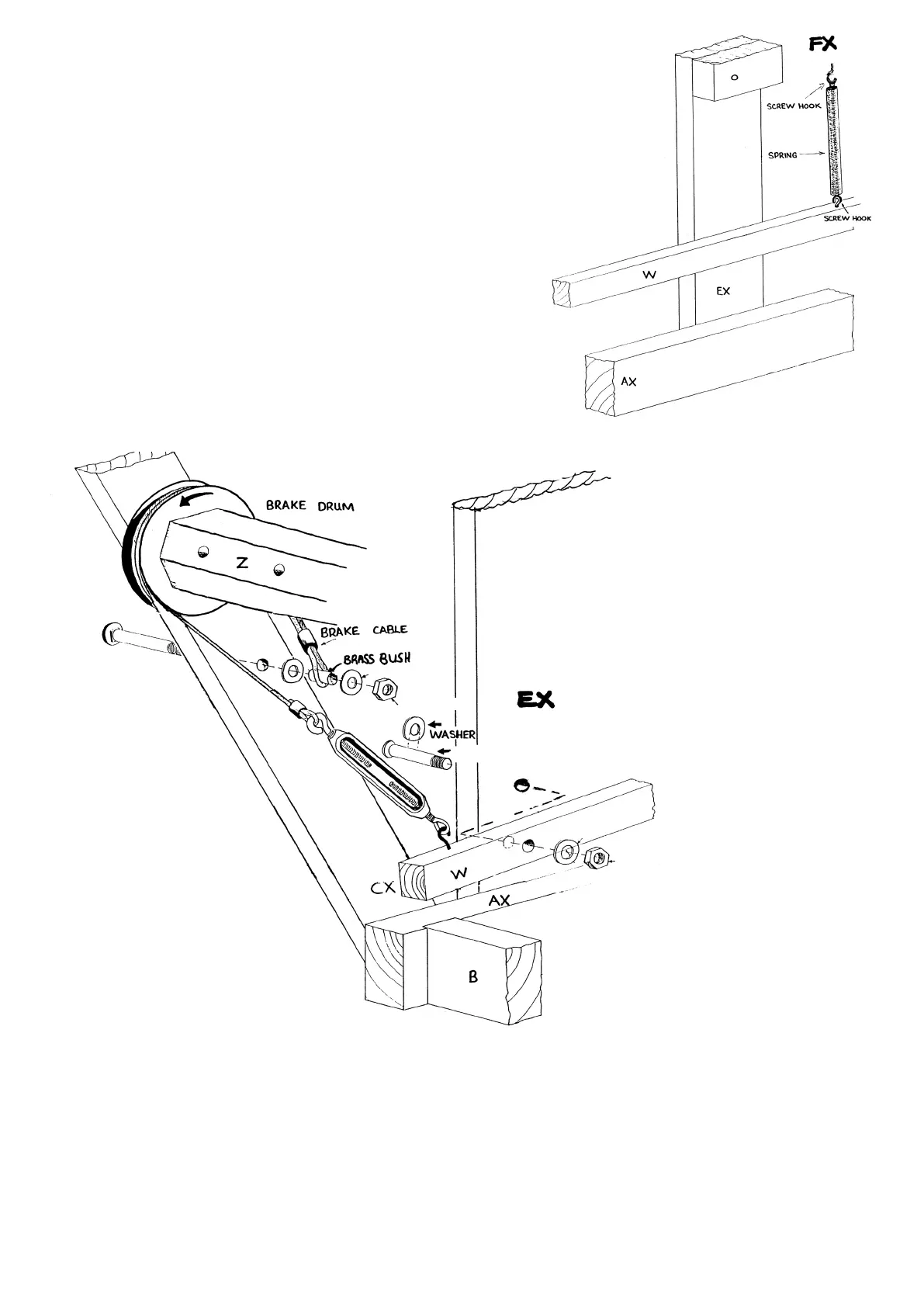
18. Fully thread two screw hooks into the brake lever W and
one screw hook into the hole underneath FX.
19. Push a M6 x 65 Cup Head Bolt through the castle side EX.
Place the brake lever W, a M6 X 16 Washer and then a M6
Nylock Nut onto the bolt. Don’t overtighten as the brake
lever must move freely.
20. Push the M6 x 40 Cup Head Bolt through the upright CX. Then locate a M6 x 16 Washer, Brass Spacer M11 x 4, the loop of the
brake cable, M6 X 16 Washer and M6 Hex Nut onto the bolt and tighten firmly. Now wind the cable around the brake drum in
the direction illustrated starting with the cable closest to the upright CX and attach the turnbuckle to the screw hook at the
end of the brake lever W.
21. Locate the spring between the screw hooks in FX and brake lever W. Adjust the turnbuckle until the cable grips the brake
drum and prevents it turning.
NOTE: If the brake does not easily release check the following:
a) That the wire rope is wound evenly on the brake drum and is not crossed over.
b) That the wire cable has been wound in the correct direction.
c) Adjust the tension on the turnbuckle until the brake holds but releases when the brake lever is depressed.
 Loading...