Do you have a question about the Ashford KIWI 2 and is the answer not in the manual?
Lists the necessary tools for assembling the spinning wheel.
Explains the various symbols used in the assembly instructions.
Assemble the flyer components, including hooks and yarn guides.
Tap wooden dowels into the ends of the treadle rail.
Loosely attach the feet to the treadle rail using bolts and barrel nuts.
Attach metal cover plates and hinges to the treadle rail with screws.
Lay the base on its back and attach treadle boards to hinges with screws.
Turn the base over and tap wooden dowels into the holes in the feet.
Attach the 'toe saver' component to the base using screws.
Secure the base to the legs with bolts and barrel nuts.
Tap wooden dowels into the main upright and position it on the base.
Secure the main upright in place using a bolt and barrel nut.
Insert polyurethane conrod joints into the ends of the conrods.
Slide the crank through the ball bearings in the main upright.
Assemble the conrod universal joint onto the crank.
Slide the wheel onto the crank and secure it with the hub pin.
Note how the rear and front conrods attach to the treadle boards.
Securely attach the conrod joints to the treadle boards using a specific sequence.
Tap the nylon bearing into the rear flyer support.
Secure flyer supports to the maiden bar with screws and attach hook/eye.
Place the maiden bar onto the upright dowels and secure with a bolt.
Install the nylon brake band, springs, and tension knob.
Locate the drive band and set up bobbins for storage and plying.
Apply oil to bearings for smoother operation and check assembly.
| Brand | Ashford |
|---|---|
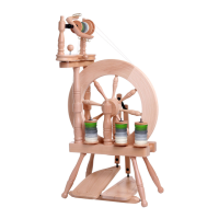
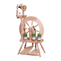
| Model | KIWI 2 |
| Type | Spinning Wheel |
| Drive Type | Double Drive |
| Drive System | Scotch Tension |
| Material | Wood |
| Weight | 5.5 kg |
| Orifice Size | 10 mm |
| Treadle | Double |
| Wheel Diameter | 45 cm |
| Finish | Natural |