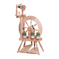
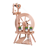
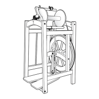
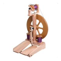
The Ashford Traveller Spinning Wheel is a fibrecraft device designed for spinning yarn, featuring a double drive system. Manufactured by Ashford Handicrafts Limited in New Zealand, this spinning wheel is made from Silver Beech wood, known for its variety of colour and grain. The manual emphasizes the importance of preparing the wood surfaces by smoothing them with sandpaper and waxing or sealing them before assembly to protect the kiln-dried wood from climatic changes and prevent staining. For a silky smooth matt finish, Ashford Wax Finish is recommended to enhance the wood's natural colours and character. The spinning wheel is also available factory-finished in clear lacquer.
Assembly requires a screwdriver, hammer, the included Allen key, scissors, candle wax, and oil. The manual provides detailed, step-by-step instructions with illustrations to guide the user through the assembly process. Key assembly steps include:
- Flyer Hooks: Threading 12 hooks into the flyer.
- Hinges: Securing two hinges to the maiden bar, noting the slot position.
- Flyer Unit: Assembling the flyer unit, checking the nylon bearing shape on each maid upright, inserting it into the correct hole, and inserting the drive belt adjusting knob into the maiden bar until it just protrudes.
- Maid Uprights: Checking the angle of nylon bearings and securing the maid uprights with screws and washers, ensuring not to overtighten. The maid uprights can be twisted to remove the bobbin. A screw eye is threaded into the side of the maiden bar.
- Bobbin and Whorl: Sliding a bobbin onto the flyer, followed by the whorl, then locating the flyer into the bearings. A screw hook is threaded into the top.
- Brake Band: Attaching the brake band by threading it through the screw eye and tying the springs as illustrated. The brake band length should be approximately 32cm (12 3/4"). The manual advises using the brake band for scotch tension spinning and storing it as illustrated otherwise.
- Treadle Rail: Checking that the holes in the base for the maiden bar supports are on the left-hand side and waxing the steel rods in the treadle rail.
- Legs and Treadle Rail: Locating the treadle rail into the holes in two legs, ensuring it rotates freely, then tapping these legs to the bottom of the holes. The remaining legs are then tapped to the bottom of their holes. All four legs are secured with screws.
- Wheel Supports: Turning the base and legs over. Securing the rear wheel supports with bolts and barrel nuts (to be tightened after the next step). The rear support is identified by a hole that goes all the way through. The front wheel supports are then secured with bolts and barrel nuts (also to be tightened after this step).
- Crank Alignment: Checking the alignment of the holes for the crank and tightening the bolts from underneath.
- Wheel and Crank Shaft: Placing the wheel in position and inserting the crank shaft. Aligning the hole in the crank shaft with the groove of the hub. Ensuring the wheel is parallel in the centre of the base and the wheel supports are tight against the hub. If not, bolts should be loosened, wheel supports adjusted, and then retightened.
- Hub Pin: Rotating the hub pin until it is a firm fit in the slot in the hub, then tapping it through the hub and crank. A Lazy Kate pin can be used as a punch to avoid damaging the hub.
- Conrod Universal Joint: Sliding the inner shell of the conrod universal joint onto the crank until it clicks into the groove, then clicking the front conrod onto the universal joint on the crank.
- Conrod Insertion: Inserting the front conrod into the large slot in the left-hand treadle board. This involves holding the conrod joint with one hand on either side of the treadle board, turning the conrod joint a 1/4 turn, stretching and sliding it into the small slot, and turning it back a 1/4 turn until it clicks into place. This sequence is repeated for the rear conrod and the right treadle board. The polyurethane conrod joints are pre-assembled in the factory.
- Maiden Bar Supports: Securing the maiden bar supports with bolts and barrel nuts.
- Top Rail: Securing the top rail to the maiden bar supports with two screws.
- Flyer Unit Alignment: Securing the flyer unit to the top rail with two screws (to be tightened shortly). Moving the flyer unit until the wheel and middle flyer pulley are aligned. Then tightening the screws and positioning a drawing pin directly beneath the drive band adjusting knob to prevent it from marking the wood.
- Threading Hook: Tying the threading hook to the front maid upright with tape.
- Drive Belt: Checking that the end of the adjusting knob is not protruding beneath the maiden bar. Wrapping the drive belt around the wheel, around the large flyer pulley, back around the wheel, and around the small bobbin pulley. The drive belt is then tied and any extra cut off. Steel lazy kate pins are tapped into the base.
Usage Features and Ratios:
The Ashford Traveller Spinning Wheel offers different ratios for spinning. To spin a finer yarn, the flyer needs to rotate faster. This can be achieved by moving the drive belt to a smaller flyer pulley and re-tensioning the drive belt. Available ratios are 7.5:1, 10:1, and 14:1. To achieve a 14:1 ratio, the brake band is wrapped over the flyer pulley and the drive belt around the bobbin pulley, a method referred to as "bobbin lead."
Maintenance Features:
Regular maintenance is crucial for the optimal performance of the spinning wheel.
- Lubrication: All points on the spinning wheel should be oiled before use, as illustrated in the manual. Candle wax is also used during assembly to make screw insertion easier.
- Troubleshooting: The manual includes a "Solutions" section to address common issues:
- Does not pull yarn in: This indicates the drive band tension is too loose. The tension knob should be tightened by 1-2mm.
- Yarn breaks: This suggests the drive band tension is too tight. The tension knob should be loosened by 1-2mm.
- Hard to treadle: This issue can often be resolved by applying candle wax to the treadle mechanism.
- Drive band falls off easily: This indicates incorrect drive band setup. The manual illustrates the correct and incorrect ways to set up the drive band.
- Strange sounds: This often points to a need for lubrication. The manual shows points to oil and apply candle wax to resolve strange sounds.
Additional Resources:
Ashford provides additional resources for users:
- YouTube Videos: How-to videos are available on their YouTube channel: www.youtube.com/user/AshfordHandicrafts.
- Facebook: Users can join their Facebook community at www.facebook.com/ashford.wheels.looms.
- The Wheel Magazine: Ashford publishes an annual fibrecraft magazine covering spinning, weaving, felting, dyeing, and knitting projects, patterns, and articles. Subscriptions are available at www.ashford.co.nz/subscribe.
Guarantee:
Ashford offers a guarantee for their products. In the unlikely event of a manufacturing fault, they will replace the item. To validate the guarantee, customers are advised to visit their website or write to them.
Technical Specifications (implied from hardware list and instructions):
- Drive System: Double drive.
- Wood Type: Silver Beech.
- Drive Band Length: Approximately 32cm (12 3/4") for the brake band.
- Ratios: 7.5:1, 10:1, 14:1.
- Hardware: Includes various screws, hooks, barrel nuts, bolts, hinges, rods, springs, and a drive band.
- Dimensions: Not explicitly stated, but the brake band length provides one measurement.
The manual is comprehensive, providing clear instructions and troubleshooting tips to ensure a smooth assembly and enjoyable spinning experience for the user.