- 5 -
BLUE = N neutral
• If the hob is electric, gas, or induction, the minimum distance between the lower part of the hood and the Hob
burners or hotplates must be at least 65 cm.
Exhaust: If a connection tube composed of two parts is used, the upper part must be placed outside or over the
lower part. Do not connect the cooker hood exhaust to any conductor used to circulate hot air or for evacuating
fumes from other appliances.
• We recommend the use of an air exhaust tube which has the same diameter as the air exhaust outlet hole (150
mm). If a pipe with a smaller diameter is used, the eciency of the product may be reduced and its operation
may become noisier.
• Installation
The following instruction should be followed to carry out the correct installation of the cooker hood.
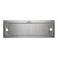
1. Mounting of the cooker hood on the lower side of the
cupboard.
2. Select the version (extraction or ltration)
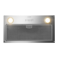
3. Before starting to x the hood, remove the anti-grease lter for easier handling:
- Open panel B as shown in Fig.2.
- Pull handle C as shown in Fig.3.
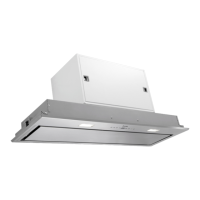
• Fitting the cooker hood into the lower part of the wall
cabinet
For all measurements relating to the cooker hood, please refer to Fig.4.
Before xing the cooker hood to the lower part of the cabinet, the following steps should be performed:
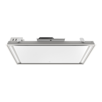
1- Remove the 4 screws E xing the two cooker hood lamps H (RHS and LHS) in place as indicated in Fig. 5A.
2- Remove the lamps H and disconnect the connectors W of the halogen lamps to make installation easier, as
indicated in Fig. 5B.
3. Make sure the thickness of the cabinet falls within the range of values listed in Fig. 5C.
Fit the cooker hood in the cabinet (Fig. 6) and make sure the 4 springs are xed in place well.
Fix the cooker hood to the cabinet securely by using a screwdriver to tighten the screws M until the
appliance is ush with the cabinet (Fig. 6).
4. Connect the connectors W of the halogen lamps again and reinstall the lamps H xing them with the 4
screws E that were previously removed.
• Ducted version
This appliance expels fumes, either through a perimeter wall or ceiling. It is therefore necessary to purchase
a non-ammable air exhaust tube (not supplied) which complies with all current legislation and connect it to
ange N (Fig.1B).
• Filter hood
Please note:
In order to transform the hood from ducted to recirculating the carbon lters must be ordered at your distributor
as an accessory.
We have two dierent types of carbon lters: Re-usable part no. ACK62260 (Fig.7) and disposable, part no.
KIT0112 (Fig.8)
- To replace the extractable active carbon lters X, pull lever outwards as shown in Fig.7
- To replace re-usable carbon lters Y, remove the brackets from their seat, pulling them outwards. (Fig.8)
Fix the bracket (included in the product packaging) to the hood using the supplied screws (Fig. 9)
USE AND MAINTENANCE
• We recommend that the cooker hood is switched on before cooking.
We also recommend that the appliance is left running for
15 minutes after the food is cooked, in order to thoroughly eliminate all contaminated air.
The eective performance of the cooker hood depends on constant maintenance; the anti-grease lter and the
active carbon lter both require special attention.
• The anti-grease lter is used to trap any grease particles suspended in the air, therefore is subject to saturation
(the time it takes for the lter to become saturated depends on the way in which the appliance is used).
-To prevent potential re hazards, the anti-grease lters should be washed a minimum of every 2 months (it is