5. Condensate Drain Preparation
Aspen recommends an auxiliary drain pan be provided and in-
stalled by the installing contractor, which should be properly
sloped, installed according to code, and terminated in an area vis-
ible to the homeowner. e auxiliary pans provide extra protec-
tion to the area under the unit should the primary and secondary
drain plug up and overow.
Install coils with the drain pan and/or casing on a at, level
surface. Slope the coil 1/4” towards the drain. Condensate lines
must be installed in accordance with building codes. It is the
contractor’s responsibility to ensure proper condensate drainage
at the time of the installation; Aspen bears no responsibility for
damages caused by improper condensate management.
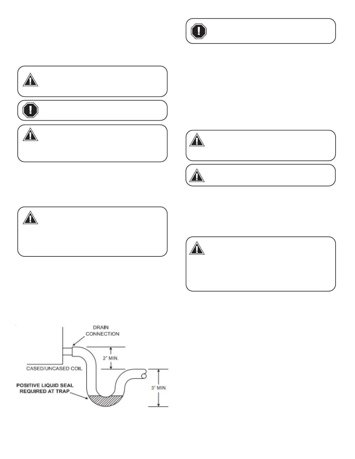
e drain lines must be installed with ¼” per foot pitch to pro-
vide free drainage. A condensate trap MUST be installed on the
primary drain line to ensure proper drainage of the condensate.
e trap must be installed in the drain line below the bottom of
the drain pan. Fig. 4-1 illustrates the typical drain trap installa-
tion. Prior to installation, ensure drain pan hole is not obstructed.
Additionally, Aspen recommends the drain lines be insulated to
prevent sweating and dripping.
Fig 5-1. Typical drain line trap setup
As expressed in our product warranty;
ASPEN WILL NOT BE BILLED FOR ANY
STRUCTURAL DAMAGES CAUSE BY
FAILURE TO FOLLOW THIS
INSTALLATION REQUIREMENT.
WARNING
Drain lines from the auxiliary drain pan
should NOT be connected to the primary
drain line of the coil.
CAUTION
Do NOT install coils with standard
temperature drain pan with oil furnaces or
applications where temperature of the
drain pan might exceed 290 °F. A metal pan should be installed.
Failure to follow this warning may result in property damage
and/or personal injury.
WARNING
Some coils have primary and secondary
drain ports on both sides of the pan to
offer installation exibility, so ensure all
threaded plugs are in present and tightened in any unused drain
ports. These may be hidden behind the coil casing access door.
Failure to do so may result in property water damage; it is the
contractor’s responsibility to ensure these plugs are present
and tight.
WARNING
- 3 -
Use Teon tape to connect the drain lines
to the threads in the drain pan. DO NOT
USE SOLVENT BASED PIPE DOPE. THIS
WILL REDUCE THE LIFE OF THE PAN.
CAUTION
e drain pan has primary (white) and secondary (red) drain
connections. If a secondary drain line is required, it should be
run separately from the primary and should terminate in a high-
ly visible location. Condensate disposal through the secondary
drain line indicates that the primary drain line is plugged and
needs cleaning. If a secondary drain line will not be provided,
plug the secondary drain. Drain plugs are NOT to be reused
without plumbers’ tape or putty. Drain line connection should be
nger tightened, then turned no more than one complete turn
as needed to ensure a rm connection. DO NOT overtighten
connection or damage may occur.
6. Coil Installation
Pipe-work including piping material, pipe routing, and installa-
tion shall include protection from physical damage in operation
and service, and be in compliance with national and local codes
and standards, such as ASHRAE 15, ASHRAE 15.2, IAPMO Uni-
form Mechanical Code, ICC International Mechanical Code, or
CSA B52. All eld joints shall be accessible for inspection prior to
being covered or enclosed.
Aer completion of eld piping for split systems, the eld pipe-
work shall be pressure tested with an inert gas and then vacuum
tested prior to refrigerant charging, according to the following
requirements:
e minimum test pressure for the low side of the system shall be
the low side design pressure and the minimum test pressure for
the high side of the system shall be the high side design pressure,
unless the high side of the system, cannot be isolated from the
low side of the system in which case the entire system shall be
pressure tested to the low side design pressure.
Field-made refrigerant joints indoors shall be tightness tested.
e test method shall have a sensitivity of 5 grams per year of
refrigerant or better under a pressure of at least 0.25 times the
maximum allowable pressure. No leak shall be detected. REFER
TO SECTION 10 FOR SYSTEM CHARGING INSTRICTIONS.
Clean coil ns with degreasing agent or mild detergent and rinse
ns clean prior to installation. Refer to Section 10 of this manual
for coil cleaning / maintenance guidance.
e refrigerant line sizes should be selected according to the
recommendations of the outdoor unit manufacturer.
The coil is manufactured with dry nitrogen
pre-charge. Release the pressure through
the Schrader valve test port prior to instal-
lation. If holding pressure is not present,
return coil to distributor for exchange.
WARNING
Refrigerant tubing must be routed to allow
accessibility for service and maintenance
of the unit.
NOTICE
For coils using A2L FLAMMABLE REFRIG-
ERANTS, when installed in a room with an
area less than that outlined in Table 12.2A
for R32 and Table 12.2B for R454B. That
room shall be without continuously operating open ames (for
Example an operating gas appliance) or other potential ignition
sources (for example an operating electric heater, hot surfac-
es). A ame providing device that may be installed in the same
space if the device is provided with an effective ame arrest.
WARNING