7. Suction Line Connection
1. Ensure suction line connection joints are burr-free and clean.
Failure to do so may increase chances of a leak and introduce
contaminants to the system. It is recommended to use a pipe
cutter to remove the spun closed end of the suction line.
2. Swage (or use a eld supplied coupler) and braze the eld
supplied refrigerant suction line tubing to the coil stub using
approved industry practices.
8. Metering Devices/Liquid Line Connection
Aspen coils are available with two kinds of metering devices a)
owrator or b) TXV. e following instructions are separated into
sections by metering device.
8A. Flowrator Coils
- 5 -
Coils designed for use with A2L Refrig-
erant are marked with a red tag on the
suction and liquid stubs. This marking
must be removed prior to brazing and shall
be replaced after brazing.
NOTICE
The sensing bulb and TXV body MUST be
protected from overheating during brazing.
The sensing bulb and TXV body must be
covered using a quench cloth or wet cloth
when brazing. Pointing the brazing ame away from the valve
and sensing bulb provide partial protection only.
WARNING
Aspen coils may include a Schrader valve
on the suction manifold. Ensure that the
Schrader valve and valve core (where
present) are protected from heat to prevent
leakage.
CAUTION
I. Installation
NOTE: Photos are for basic illustration / reference purposes only.
Actual equipment conguration may differ from that shown.
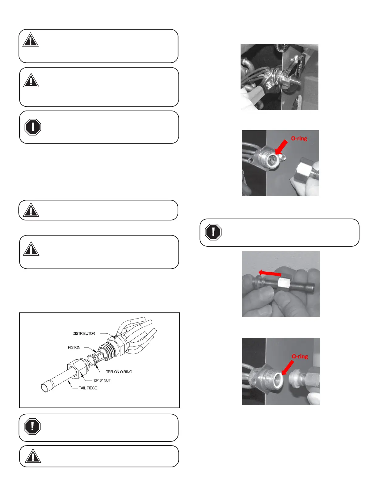
I-1. Disassemble owrator body using two wrenches and
unscrewing with a counterclockwise motion.
I-2. Replace the Teon O-ring (located between the halves).
Discard Schrader if present.
I-3. Slide the attachment nut onto the liquid line stub out.
I-4. Braze the stub-out portion to the liquid line and let cool.
I-5. Taking care that the white Teon seal is still in place inside the
owrater body, rmly seat the stub and screw the attachment nut
to owrater body.
I-6. Tighten nut using no more than 10 -lbs of torque. A are
nut open end wrench is recommended to evenly distribute the
force across all six sides of the nut to ensure piston body is not
deformed.
Do not attempt to touch brazed joints
while hot. Severe burns may result.
WARNING
Coils designed for use with A2L Refrig-
erant are marked with a red tag on the
suction and liquid stubs. This marking
must be removed prior to brazing and shall
be replaced after brazing.
NOTICE
Fig 8A-1. Flowrator assembly components
Use Piston sizes recommended by the out-
door unit manufacturer whenever possible.
The piston should be sized according to
the capacity of the outdoor unit.
CAUTION
Failure to install the proper piston can
lead to poor system performance and
possible compressor damage.
WARNING
Be aware of the Teon O-ring. Be sure to
replace the O-ring to attain a proper seal.
(The Teon O-ring is located between the
two halves of the owrator)
CAUTION
 Loading...