- 9 -
TXV Coils:
If the unit is equipped with a xed TXV, add refrigerant until the
subcooling measures at the outdoor unit liquid line matches the
subcooling recommendations of the outdoor manufacturer. If the
charge is unavailable charge the unit to a subcooling value of 8°F
+/- 1°F.
If the unit is equipped with an adjustable TXV, add refrigerant
until the subcooling measures at the outdoor unit liquid line
matches the subcooling recommendations of the outdoor manu-
facturer. If the charge is unavailable charge the unit to a subcool-
ing value of 8°F +/- 1°F.
1. If subcooling and superheat are low, adjust TXV to 8°F +/-
1°F superheat, then check subcooling.
2. If subcooling is low and superheat is high, add charge to
raise subcooling to 8°F +/- 1°F then check superheat.
3. If subcooling and superheat are high, adjust TXV valve to
8°F +/- 1°F superheat, then check subcooling.
4. If subcooling is high and superheat is low, adjust TXV
valve to 8°F +/- 1°F superheat and remove charge to lower
the subcooling to 8°F +/- 1°F.
e TXV should NOT be adjusted at light load / ambient condi-
tions of 60°F or below.
11. Coil Cleaning Instructions
Aspen cased coils are equipped with a two-piece panel door to
allow for cleaning and maintenance access. Remove one or both
doors to access the coil for cleaning.
For both copper and aluminum tube coils, it is recommended
to ush with the coil with water. ere are coil cleaners that are
available that contain corrosive chemicals, such as, but not lim-
ited to, chlorine and hydroxide, that are not approved for use on
Aspen copper and aluminum tube coils.
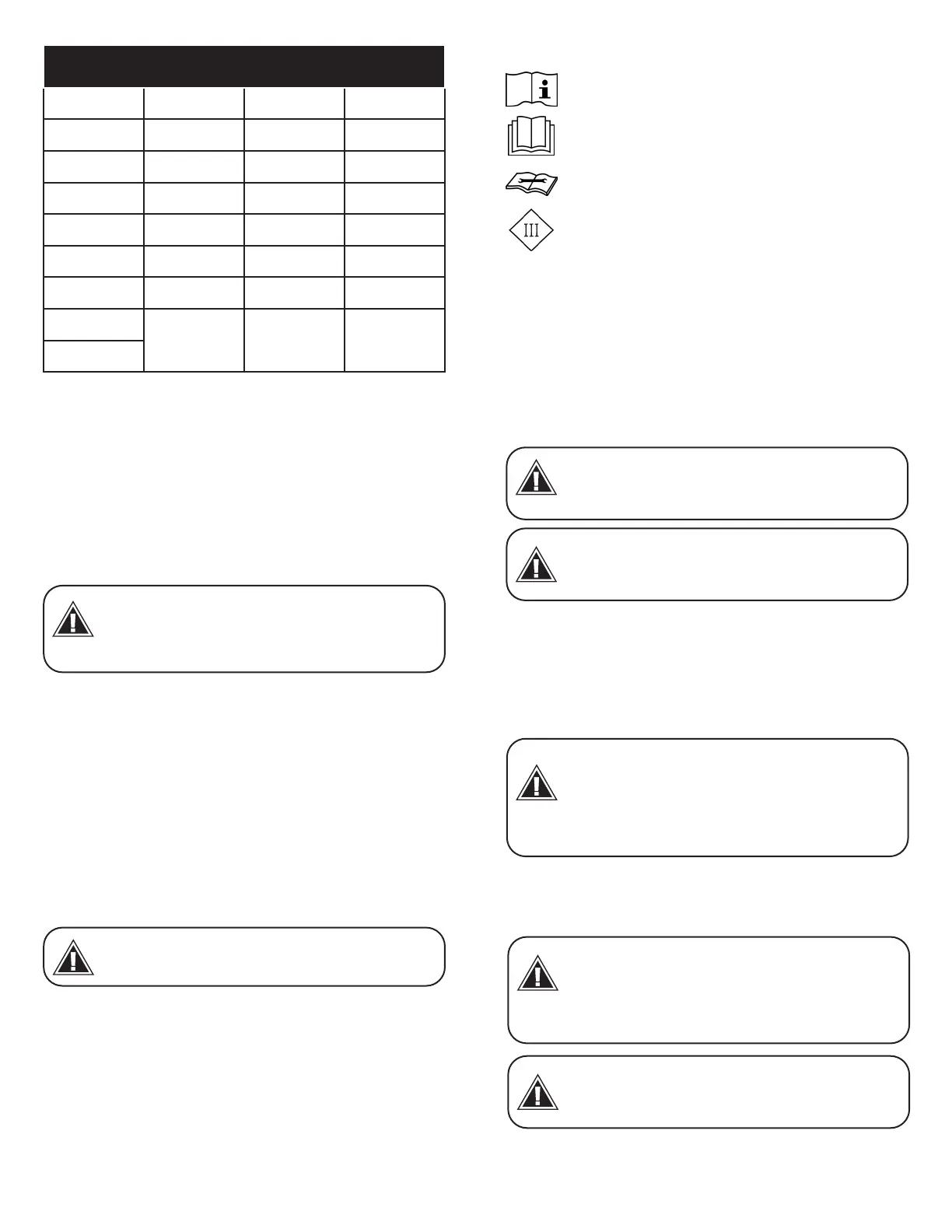
Outdoor
Temp
Superheat
°F D.B. Min Nom Max
65 30 35 40
70 26 30 34
75 21 25 29
80 17 20 23
85 12 15 18
90 8 10 12
95
4 5 7
100
12. A2L Coils and Refrigerant Detection Systems
12.1 Installation, Service, Maintenance & Repair
Instructions
Products designed for use with A2L Refrigerants are equipped
with a refrigerant leak detection system (which includes an A2L
Sensor, a Mitigation Control Board, and Harnesses) which must
be wired to the furnace as specied in the Wiring Diagram.
e A2L Sensor must be installed and powered for service. On
cased coils ensure that the strain relief is installed in the through
the knockout hole in the access panel.
For mechanical ventilation, the lower edge of the air extraction
opening where air is exhausted from the room shall not be more
than 100 mm above the oor. e location where the mechani-
cal ventilation air extracted from the space is discharged shall be
separated by a sucient distance, but not less than 3 m, from the
mechanical ventilation air intake openings, to prevent recircula-
tion to the space.
False ceilings or drop ceilings may be used as a return air plenum
only if a refrigerant detection system is provided in the appliance
and any external connections are also provided with a sensor im-
mediately below the return air plenum duct joint.
12.1.1 Qualication of workers
Only technicians with training carried out by national training
organizations or manufacturers that are accredited to teach the
When adjusting the TXV, the valve stem
or adjusting screw should not be adjusted
more than a ¼ turn at a time. To adjust
superheat, turn the valve stem clockwise
to increase and counterclockwise to decrease.
NOTICE
Do not use means to accelerate the
defrosting process or to clean, other than
those recommended by the manufacture.
WARNING
Read the precautions in this manual carefully before
operating the unit.
Read the instructions in this manual carefully before
operating the unit.
Read the instructions in this manual carefully before
servicing the unit.
Read the instructions in this manual carefully before
wiring the unit.
Disconnect ALL power before servicing
or installing this unit. Multiple power
sources may be present. Failure to do so
may cause property damage, personal injury, or death.
WARNING
When using FLAMMABLE
REFRIGERANTS, LEAK DETECTION
SYSTEM installed. Unit must be powered
except for service.
WARNING
Refrigerating pipe or components are
installed in a position where they are
unlikely to be exposed to any substance
which may corrode refrigerant contain-
ing components, unless the components are constructed of
materials which are inherently resistant to being corroded or are
suitably protected against being so corroded.
WARNING
Auxiliary devices which may be a
POTENTIAL IGNITION SOURCE shall not
be installed in the duct work. Examples of
such POTENTIAL IGNITION SOURCES are
hot surfaces with a temperature exceeding 700°C and electric
switching devices.
WARNING
Only auxiliary devices approved by the
appliance manufacturer or declared
suitable with the refrigerant shall be
installed in connecting ductwork.
WARNING


 To Next Page