Care must be taken to ensure all connection joints are burr-free
and clean. Failure to do so may increase chances of a leak. It is
recommended to use a pipe cutter to remove the spun closed end
of the suction line.
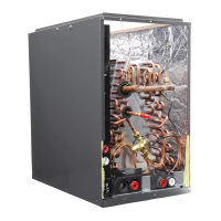
To reduce air leakage, rubber grommets may be present where the
lines pass through the coil case. To avoid damage, remove grom-
mets prior to brazing by sliding over the lines. Use a quenching
cloth or allow the lines to cool before reinstalling the grommets.
Use of wet rags/quenching cloth is highly recommended to pre-
vent weld-related damage to the casing and Schrader valve (if
present).
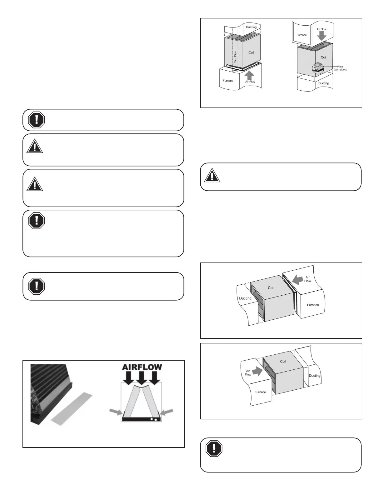
Can be installed in either an upow or a downow application.
6A. Vertical Upow/Downow Installation (CA, CC, CE)
To set up coils for downow application, install the two 3” wide by
16” long galvanized metal plates on the outside of the coil, against
the ns on each side of the coil as shown in Fig. 5A-3. ese plates
are included with the CM coil and are purchased separately
on the CA, CC, and CE models.
Do NOT exceed 350 cfm/ton of airow for downow
applications.
Coil should be installed on the discharge
side of the furnace.
CAUTION
Aspen coils may include a Schrader valve
on the suction manifold. Ensure that the
Schrader valve and valve core (where
present) are protected from heat to
prevent leakage.
NOTICE
- 4 -
To position the coil on furnace:
1. Locate the air outlet of the furnace
2. Adjust anges accordingly and position the coil over or
under the furnace outlet.
3. Place ductwork over the casing.
Refer to Furnace/Air Handler manufacturer literature for specic
coil installation guidelines and recommendations.
6B. Horizontal Installation (CE ONLY)
Multi-position coils are shipped from the factory such that they
can be installed in both vertical and horizontal applications with-
out changes to the coil. When installing these coils in the hori-
zontal application, the details mentioned in this section must be
followed.
Multi-position coils come equipped with a horizontal drain pan
(Plastic/Metal). e plastic drain pan is protected from high tem-
peratures by a metal plate at the apex end of the coil.
Refer to Furnace/Air Handler manufacturer literature for
specic coil installation guidelines and recommendations.
CAUTION
CAUTION
Multi-position Coils are shipped from the
factory for specic horizontal applications
(horizontal right or horizontal left). Installer
must ensure that the coil is installed in the orientation for which
it was intended (horizontal drain pan side down). Failure to
follow these instructions might lead to property and equipment
damage.
CAUTION
When installing in conjunction with a gas
furnace in a vertical orientation, ensure
that there is 2” gap between the bottom of
the drain pan and the outlet of the furnace.
CAUTION
Fig 6A-1. Upow Application Fig 6A-2. Downow
Application
When installing uncased coil on top of fur-
nace a eld fabricated 2.0” to 6.0” spacer
(placed between the furnace exit and the
inlet of the evaporator) should be installed.
Fig 6B-1. Horizontal Left Application
Fig 6B-2. Horizontal Right Application
NOTICE
As mentioned elsewhere in this document,
in an application involving oil furnace
a metal drain pan MUST be used. Coils
installed on an oil furnace must have a
minimum of six inches clearance between the top of the furnace
and bottom of the drain pan.
WARNING
Fig 6A-3. Metal Plate location for a Downow / Counterow
Application
Due to higher designed radiant heat, a eld
fabricated 6.0” spacer (placed between the
furnace exit and the inlet of the evapora
tor) should be installed when matching up an Aspen coil with an
ultra-low NOx (ULN) furnace.
CAUTION