- 8 -
III-7. Slide attachment the nut onto the liquid line stub out
(See 7A, I-3)
III-8. Braze the stub-out portion to the liquid line and let cool.
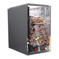
III-9. Remove the addition-
al Teon O-ring seal from the
box and place on the shoulder
just inside the TXV inlet port.
Screw the nut attached to the
stub-out portion of the owra-
tor body onto the inlet port of
t h e T X V.
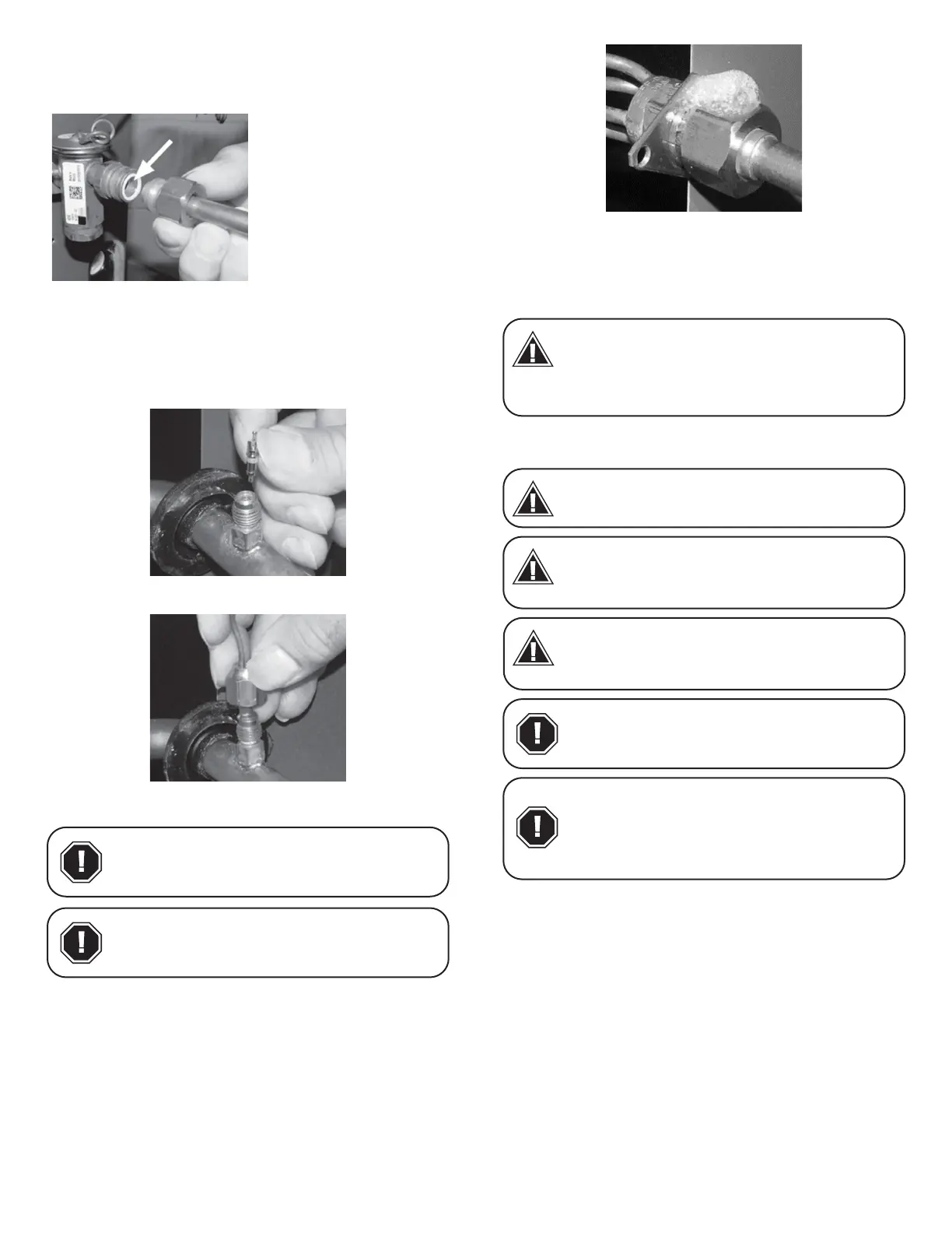
III-10. Tighten all connections taking care to use proper back up.
Tighten the nut to a torque of approximately 10-30 -lbs.
III-11. Remove the valve identication sticker from the valve and
place it adjacent to the Aspen model number on unit name plate.
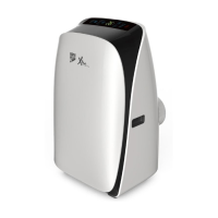
III-12a. Some Aspen coils come with a Schrader valve on the
suction line. If a Schrader port is present:
A. Remove the valve stem from the Schrader port mounted on
the suction line.
B. Screw are nut on TXV equalization tube on to the Schrader
valve stem.
9. Leak Check
1. Following outdoor unit manufacturer instructions and
recommendations, charge the system with dry nitrogen to
a maximum pressure of 150 PSIG.
2. Check all brazed and screw-on line connections by
applying a soap solution to the joint. A leak will produce
bubbles in the soap solution.
3. If any leaks are discovered, relieve system pressure and
repair leaks. Repeat steps 1-3.
4. With no leaks or weak connections present, evacuate the
system and charge as per the outdoor unit manufacturer
instructions and specications.
10. System Charging
Where addition of charge is required to complete installation, in-
structions on how to determine the additional REFRIGERANT
CHARGE and how to complete the REFRIGERANT CHARGE
on the label provided by the outdoor unit manufacturer adjacent
to the nameplate if the compressor bearing unit. Interconnecting
refrigerant piping length and diameter shall be taken into consid-
eration.
Flowrator coil:
Add refrigerant until the superheat measured at the outdoor unit
suction/vapor line matches the superheat from the chart on the
next page.
When handling or manipulating the equal-
izer tube, take great care not to kink or
make extreme bends in the tubing.
CAUTION
Using a non-bleed expansion valve may re-
quire the use of a hard-start kit. Follow the
outdoor unit manufacturer’s guidelines.
CAUTION
Test pressures for A2L refrigerants, eld
made refrigerant joints shall have a sensi-
tivity of 5 grams per year of refrigerant or
at least 25 times the maximum allowable
pressure. No leaks shall be detected in the
systems.
NOTICE
Units designed for use with R410a
refrigerant MUST be charged with R410a
refrigerant.
WARNING
Units designed for use with R32
refrigerant MUST be charged with R32
refrigerant. Ensure that the R32 sensor is
installed correctly and is operational.
WARNING
Units designed for use with R454B
refrigerant MUST be charged with R454B
refrigerant. Ensure that the R454B sensor
is installed correctly and is operational.
WARNING
An improperly charged system will likely
cause loss in system performance and
may damage the compressor.
CAUTION
Refer to outdoor unit manufacturer
charging guidelines and recommenda-
tions. The recommendations given below
are general in nature and are NOT to
supersede outdoor unit manufacturer
specications.
CAUTION
 Loading...