II. Piston Replacement
NOTE: Photos are for basic illustration / reference purposes only.
Actual equipment conguration may differ from that shown.
During some installations, a piston change may be required. If
so, the installer MUST change the piston. Use piston sizes rec-
ommended by the outdoor unit manufacturer. If a sizing chart is
not available, use the piston size chart provided below to size the
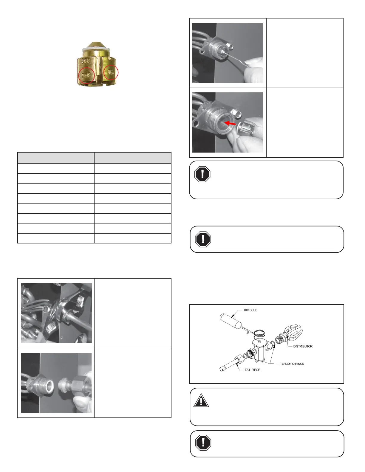
required piston. e size of the piston is stamped on the piston
body (Fig 7A-2).
Use the chart below when matching coil with an outdoor unit
with a dierent nominal capacity than the coil.
II-1. Evacuate the system as per manufacturer guidelines and rec-
ommendations.
II-2. Turn the 13/16” nut once to release any residual pressure in
the coil.
Outdoor Unit Capacity R410A Orice Size
12,000 N/A
18,000 0.049
24,000 0.055
30,000 0.059
36,000 0.068
42,000 0.074
48,000 0.080
60,000 0.089
II-5. Pull the piston out using
a small wire or pick. Verify
the piston size (size is
typically stamped on the body
of the piston - Fig 7A-2).
If a dierent piston size is
required by the outdoor unit
manufacturer, replace the
piston using the small wire
provided with the piston kit.
II-6. Replace the piston with
one of the correct size. Do not
force the new piston into the
body. Make sure the piston
moves freely in body.
- 6 -
Pay close attention to the piston orienta-
tion. The pointed end of the piston MUST
go into the distributor body, towards the
coil. Failure to ensure this orientation will
cause the piston to be bypassed during operation which might
damage the outdoor unit.
CAUTION
Be aware of the Teon O-ring. Be sure to
replace the O-ring to attain a proper seal.
(The Teon O-ring is located between the
two halves of the owrator).
CAUTION
Fig 8B-1. Components of a typical TXV assembly
The sensing bulb and TXV body MUST be
protected from overheating during brazing.
The sensing bulb and TXV body must be
covered using a quench cloth or wet cloth
when brazing. Pointing the brazing ame away from the valve
and sensing bulb provide partial protection only.
WARNING
Ensure that the TXV selected is compatible
with the refrigerant used in the outdoor
system. The TXV body is marked with
R410A, R454B, or R32.
CAUTION
Fig 7A-2
II-7. Assemble the two halves correctly and ensure that the Tef-
lon O-ring is present between the two halves (See I-5). Slide the
13/16” nut onto the distributor body.
II-8. Tighten the nut to a torque of approximately 10 -lbs. Do
NOT overtighten the nut. Overtightening could crack the nut
and/or impede the piston movement during operation.
II-9. If present, slide the rubber grommet back to position to pre-
vent air leakage.
8B. TXV Coils
II-3. Aer ensuring that the
coil is free of any residual
pressure, disassemble the
owrator body completely
using two wrenches. Take
great care not to distort the
feeder tubes. e wrench used
to clasp the nut should be
turned in counterclockwise
direction to unscrew the nut.
II-4. Slide the 13/16” nut over
the lineset and separate the
two halves of the owrator.


 To Next Page