I. TXV Bulb Horizontal Mounting
e orientation and location of the TXV bulb has a major inu-
ence on the system performance.
It is recommended that the TXV bulb be installed parallel to the
ground (on a horizontal plane). e bulb position should be at 2
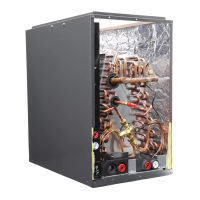
o’clock or 10 o’clock. Fig. 7B-2 shows the recommended position
for the TXV bulb installation in the horizontal plane.
e TXV sensing bulb SHOULD be mounted on the suction line
approximately 6” from the TXV or coil housing using the metal
clamp provided. In order to obtain a good temperature reading
and correct superheat control, the TXV sensing bulb must con-
form to ALL of the following criteria:
1. e sensing bulb MUST be in direct and continuous
contact with the suction line.
2. e sensing bulb should be mounted horizontally on the
suction line.
3. e sensing bulb MUST be mounted at the 2 o’clock or
10 o’clock position on the circumference of the suction
line.
4. e sensing bulb MUST be insulated from outside air.
A properly mounted sensing bulb will prevent false readings
caused by liquid refrigerant that may have formed inside the suc-
tion/vapor line. Insulation will protect the sensing bulb from false
readings due to contact with warm air.
II. TXV Bulb Vertical Mounting
III. Field-Installed TXV Retrot
NOTE: Photos are for basic illustration / reference purposes only.
Actual equipment conguration may differ from that shown.
When installing an expansion valve, it is not necessary to slide the
coil out of the housing.
The valves should be sized according to
the capacity of the outdoor unit. Failure
to install the right valve can lead to poor
performance and possible compressor
damage.
CAUTION
Ensure that the TXV bulb is in direct
contact with the suction/vapor line. Gap
between the bulb and tube should be
avoided. Failure to do so will impair the
proper functioning of the TXV valve.
CAUTION
- 7 -
Fig 8B-2. Recommended location
for horizontal TXV bulb mount
Bulb position at 2 o’clock or 10 o’clock
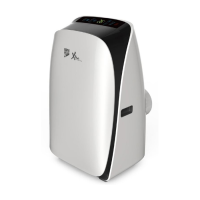
As recommended in Section 7B-I,
the TXV sensing bulb should be
mounted in a horizontal plane
in relation to the suction/vapor
line. However, some installation
congurations may require that the
sensing bulb be mounted vertically.
In this instance, place the bulb
opposite the piping wall being
hit by refrigerant and oil leaving
the distributor tubes, and with
capillary tubes directed upwards as
shown in Fig. 7B-3.
Fig 7B-3.
Recommended location
for vertical TXV bulb mount
If the TXV sensing bulb is mounted
vertically; the capillary MUST be directed
upwards. The bulb must be mounted on
the wall opposite to that being directly
hit by the refrigerant and oil leaving the distributor tubes.
CAUTION
Do not attempt to touch brazed joints
while hot. Severe burns may result.
WARNING
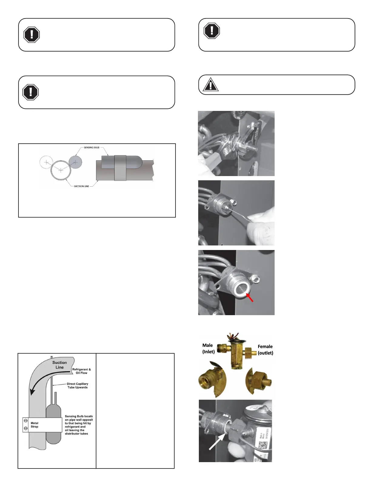
III-1. Disassemble the owrator
body using two wrenches. Un-
screw the body with a counter-
clockwise motion.
III-2. Remove the existing ow-
rator piston using a small wire
or pick.
III-3. Replace the Teon O-ring
seal in place (located between
the halves).
III-4. Inspect the TXV box to conrm that the valve is compatible
with the refrigerant in the system.
III-5. Remove the valve from
the box and note the location
of the inlet side (threaded male
port) and the outlet side (fe-
male swivel nut port).
III-6. Aer ensuring that the
Teon O-ring seal is still in
place inside the owrator body,
screw the female swivel nut
onto the owrator body.
 Loading...