32 33
English
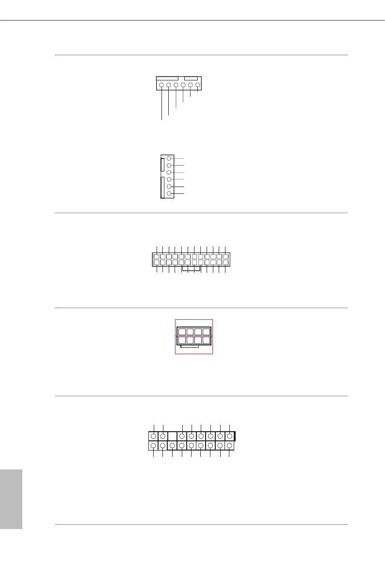
Front and Rear Fan
Connectors
(4-pin FR NT_FAN1)
(see p.7, No. 11)
(4-pin FRNT_FAN2)
(see p.7, No. 12)
(4-pin FRNT_FAN3)
(see p.7, No. 13)
(4-pin FRNT_FAN4)
(see p.7, No. 14)
(4-pin R EAR_FAN1)
(see p.7, No. 55)
FAN1 SENSOR
FAN_SPEED_CONTROL
12V(FAN_VOLTAGE)
GND
FAN2 SENSOR
NC
FAN_SPEED
FAN_SPEED_CONTROL
FAN_VOLTAGE
GND
SENSOR
NC
6
5
4
3
2
1
Please connect fan cables to the
fan connectors and match the
black wire to the ground pin.
All fans support Fan Control.
ATX Power Connector
(24-pin ATX PWR1)
(see p.7, No. 5)
3V
3V
GND
GND
5V
5V
GND
PWROK_PS
5VSB
12V
12V
3V
121
13
24
3V
-12V
GND
PSON#
GND
GND
GND
5V
5V
5V
GND
N/A
is motherboard provides a
24-pin ATX power connector.
To use a 20-pin ATX power
supply, please plug it along Pin
1 and Pin 13.
ATX 12V Power
Connectors
(8-pin ATX12V1)
(see p.7, No. 4)
(8-pin ATX12V2)
(see p.7, No. 3)
4
8
1
5
12V
GND
is motherboard provides
two 8-pin ATX 12V power
connectors.
TPM Header
(17-pin TPM1)
(see p.7, No. 40)
1
GN D
SMB_DATA_MAIN
LAD2
LAD1
GN D
S_PWRDWN #
SERIRQ #
GN
D
P CICL K
P CIRST #
LAD3
+3 V
LAD0
+3VS B
GN D
FRAM E
SMB_CLK_MAIN
is connector supports
Trusted Platform Module
(TPM) system, which can
securely store keys, digital
certicates, passwords, and
data. A TPM system also helps
enhance network security,
protects digital identities, and
ensures platform integrity.

 Loading...