February 2012 8 80-0180-351 Rev. E
STEP 3 CONFIGURE FOR LOCK SERIES
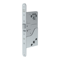
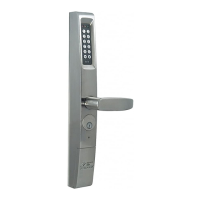
Mortise Latch Application: 3090-01 for 4500/4900
(including 8300/8400 Exit Devices)
Configure the supplied cam plug to match the hand of door. Insert camplug
into latch case with notch on the cam plug aligned with latch case set screw.
Tighten set screw and secure with the two brass cam plug screws.
CVR Exit Device Application: 3090-01 for 8500/8600
Install Tailpiece adapter on the vertical rod and fasten with Phillips screw as
shown.
FIG. 9
Left Hand Reverse
(LHR)
FIG. 7
Right Hand Reverse
(RHR)
FIG. 8
80-0180-351 Rev. E 9 February 2012
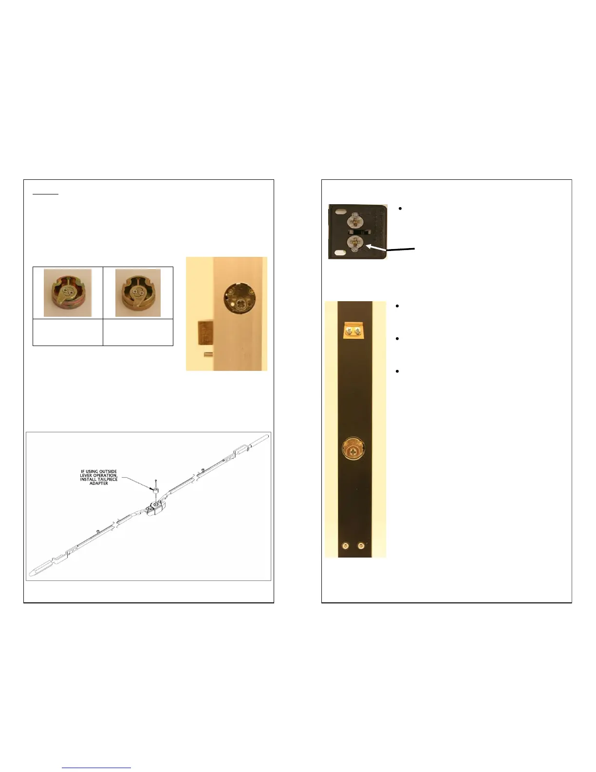
RIM Exit Device Application: 3090-01 for 8700/8800
On the back side of the exit device, remove only
the lower Phillips head screw, depending on hand
of door, to free up the cylinder actuator for use.
(FIG. 10)
FIG. 10
MS 1850 Application – 3090-02 for MS
®
Series Deadbolt
Two (2) brass hex head screws and the set screw
from the MS1850 will fasten the cam plug to the
MS1850. (FIG. 11)
For MS
®
Deadbolt, insert Cam Plug into lock case
with notch on the cam plug aligned with lock case
set screw.
Tighten set screw and secure with the two (2) brass
cam plug screws. Cam Plug must be positioned
below door surface.
FIG. 11
CYLINDER ACTUATOR SCREW
 Loading...